

The drive toward grid decarbonization and maximized electrical efficiency has intensified the scrutiny on distribution network losses. Within any utility or industrial power system, transformers account for a significant percentage of transmission and distribution energy waste. These losses are categorized into load losses (copper losses), which fluctuate based on the current demand, and no-load losses (iron losses), which remain constant as long as the equipment is energized. Because transformers operate continuously, no-load losses accumulate 24 hours a day, 365 days a year, representing a massive baseline energy drain. Upgrading the core material from conventional cold-rolled grain-oriented (CRGO) silicon steel to advanced amorphous metals is the most effective engineering intervention to mitigate this perpetual waste. This analysis explores the metallurgical physics, manufacturing architecture, and Total Cost of Ownership (TCO) mechanics of the amorphous alloy transformer.
The Physics of No-Load Losses: Hysteresis and Eddy Currents
To understand the structural advantage of amorphous metals, engineers must first deconstruct the mechanics of iron losses within a power transformer core. No-load losses are predominantly composed of hysteresis losses and eddy current losses. Hysteresis loss occurs due to the continuous realignment of magnetic domains within the core material. In a standard 50Hz or 60Hz alternating current (AC) grid, the magnetic field reverses direction 100 or 120 times per second. Overcoming the internal molecular friction to constantly flip these magnetic domains requires energy, which is dissipated as heat.
Eddy current loss, conversely, is governed by Faraday's Law of Induction. The alternating magnetic field induces localized, circulating electrical currents within the conductive steel core itself. These currents flow in closed loops, encountering the electrical resistance of the steel and generating ohmic heating. Conventional transformer designs mitigate eddy currents by laminating the CRGO steel—slicing it into thin sheets (typically 0.23mm to 0.30mm thick) and applying a microscopic insulating oxide layer to interrupt the circulating current paths. However, the crystalline structure of CRGO steel inherently limits how far these losses can be reduced.
Metallurgical Differentiation: Crystalline vs. Amorphous Structures
Amorphous alloy, often referred to as metallic glass, fundamentally breaks the constraints of traditional metallurgy. Conventional CRGO silicon steel is processed through slow cooling and rigorous rolling techniques, which align its atomic structure into a highly organized, predictable crystalline lattice. This ordered structure requires a defined amount of coercive force to reorient its magnetic domains.
Amorphous metal is manufactured using a rapid solidification process known as melt spinning. Molten alloy (typically a composite of iron, silicon, and boron) is ejected onto a super-cooled, high-speed rotating copper wheel, cooling at an astonishing rate of approximately one million degrees Celsius per second. This instantaneous cooling prevents the atoms from forming a crystalline lattice. Instead, the atoms are frozen in a random, disorganized state—similar to the atomic structure of liquid glass.
This random atomic structure presents virtually zero friction to magnetic domain realignment, drastically minimizing hysteresis loss. Furthermore, the melt spinning process produces ribbons of extraordinary thinness—typically 0.02mm to 0.03mm, which is roughly one-tenth the thickness of standard CRGO laminations. Combined with a naturally higher electrical resistivity (roughly three times that of silicon steel), the extreme thinness of the amorphous ribbon suppresses eddy currents to negligible levels. The net result is a magnetic core that reduces overall no-load losses by 70% to 80% compared to high-grade CRGO cores.
Manufacturing Architecture and Core Design Challenges
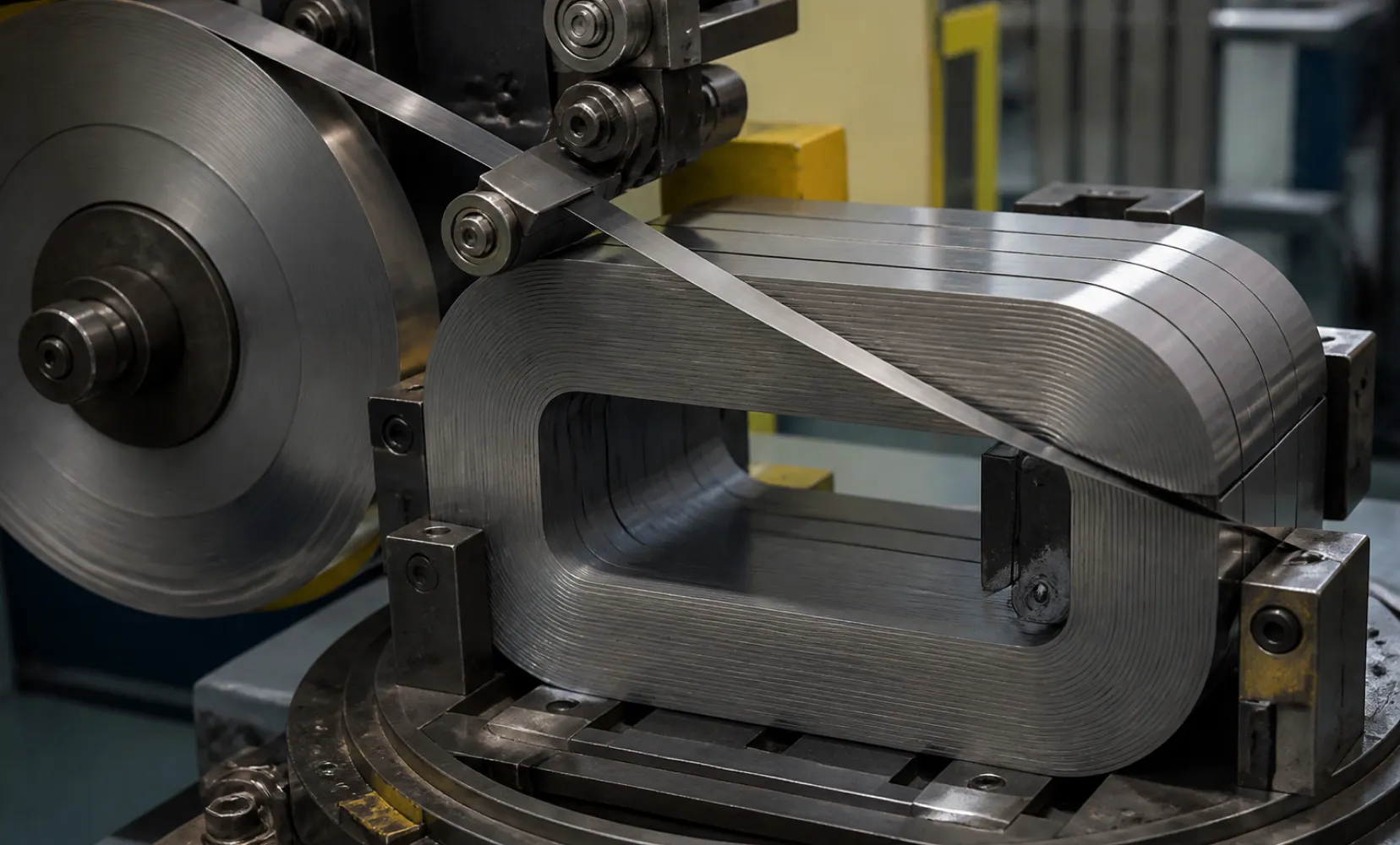
Integrating amorphous ribbons into a functional transformer requires overcoming significant mechanical challenges. Amorphous alloy is notoriously hard and brittle, making it highly sensitive to mechanical stress. Standard transformer manufacturing techniques involving stacking, punching, or cutting step-lap joints—which work perfectly for ductile CRGO steel—will shatter amorphous ribbons and severely degrade their magnetic properties.
To preserve the magnetic integrity, amorphous cores are exclusively manufactured using a wound core architecture. The ultra-thin ribbons are continuously wound into a rectangular or circular form. Because any mechanical stress induced during the winding process increases hysteresis loss, the assembled cores must undergo a rigorous stress-relief annealing process inside a specialized high-temperature vacuum furnace, often in the presence of a strong direct current (DC) magnetic field to establish a unidirectional magnetic axis.
Another engineering consideration is the saturation magnetic flux density. Amorphous alloys typically reach magnetic saturation at around 1.56 Tesla, which is lower than the 1.9 Tesla saturation point of high-grade CRGO steel. To compensate for this lower flux density and prevent the core from saturating under nominal voltages, the physical cross-sectional area of the amorphous core must be expanded. Consequently, an amorphous alloy transformer will generally have a larger physical footprint and a higher total weight than a conventional unit of identical kVA rating.
Thermal Performance and Overload Capability
The dramatic reduction in iron losses inherently alters the thermal dynamics of the equipment. Because the core generates roughly one-quarter of the heat of a standard CRGO core during idle or low-load operation, the baseline operating temperature of the transformer is significantly lower. This provides an expanded thermal margin during peak demand cycles.
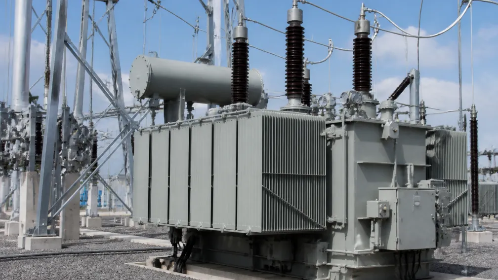
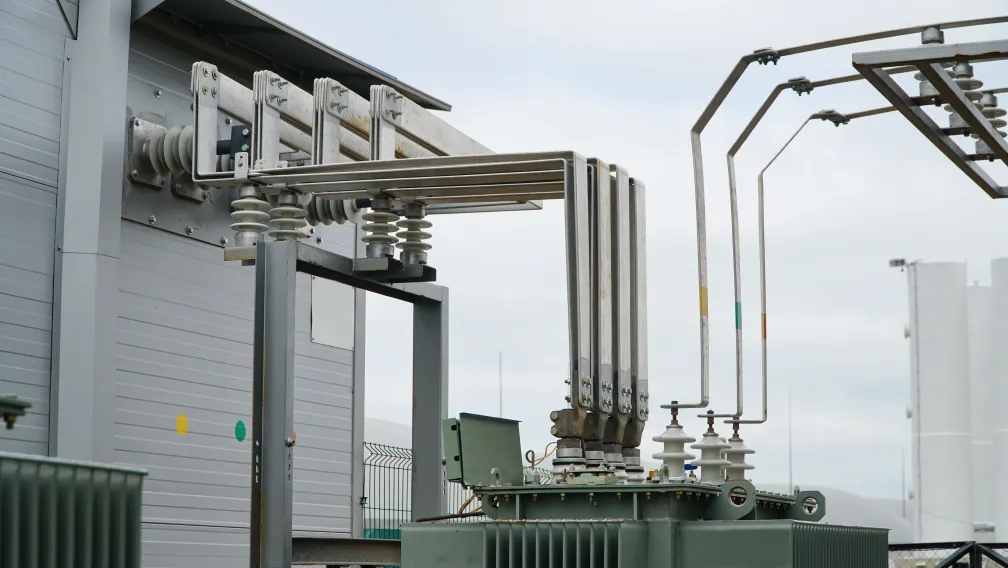
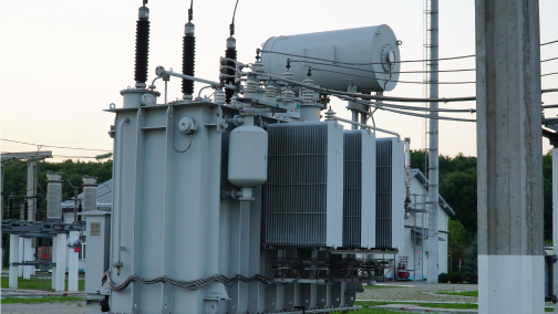
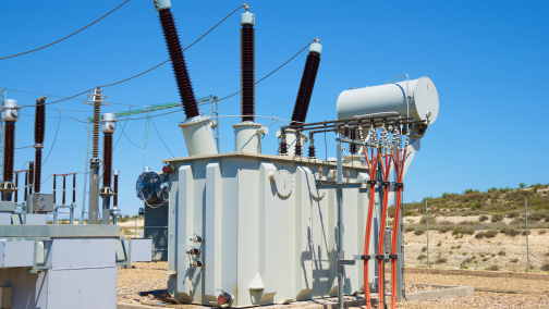
Whether deployed as an oil-immersed transformer for outdoor substations or a cast-resin dry-type transformer for indoor commercial basements, the reduced core heating slows the degradation rate of the solid insulation materials (such as cellulose paper or epoxy resin). A cooler baseline extends the statistical lifespan of the dielectric system, reducing the risk of premature insulation failure and extending the asset's operational longevity beyond the standard 30-year utility benchmark. Furthermore, the lower operating temperature reduces the burden on auxiliary cooling systems, such as substation HVAC units or forced-air fan arrays.
Harmonic Tolerance in Renewable Energy Applications
Modern grids are increasingly saturated with non-linear loads—variable frequency drives, UPS systems, and large-scale solar photovoltaic (PV) inverters—which inject severe harmonic distortion into the distribution network. High-frequency harmonics rapidly escalate eddy current losses in standard transformers, as eddy current heating is proportional to the square of the frequency.
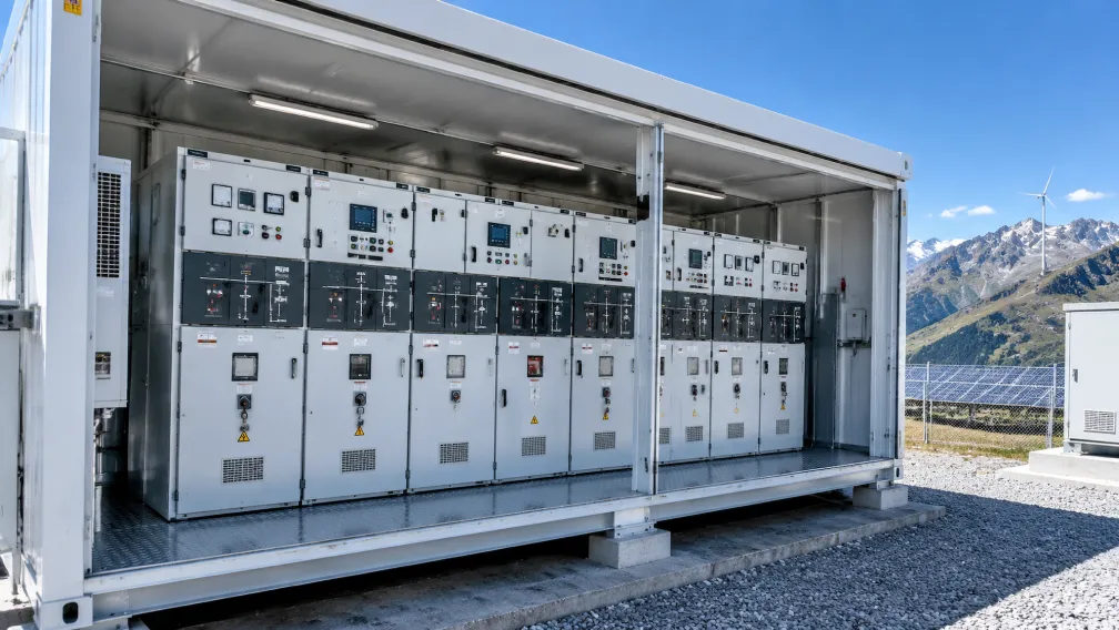
Because amorphous ribbons are extremely thin and possess high electrical resistivity, their eddy current losses remain exceptionally low even when subjected to the high-frequency harmonics generated by utility-scale solar arrays. This makes the amorphous core a technically superior specification for renewable energy integration and electric vehicle (EV) charging stations, where standard CRGO cores would experience dangerous overheating and require severe thermal derating to survive.
Total Cost of Ownership (TCO) and Capitalization of Losses
The procurement of amorphous transformers requires a shift from capital expenditure (CAPEX) evaluation to Total Cost of Ownership (TCO) modeling. Due to the complex manufacturing processes and specialized materials, an amorphous unit typically carries an initial CAPEX premium of 15% to 30% over a standard CRGO equivalent. However, utility engineers evaluate transformers using the Loss Capitalization Formula (TCO = Purchase Price + (A × No-Load Losses) + (B × Load Losses)).
The 'A' factor, which monetizes the cost of continuous no-load losses over the transformer's lifespan, heavily favors the amorphous design. In regions with high electricity tariffs, or in facilities operating 24/7 (such as semiconductor fabs and hyperscale data centers), the continuous 80% reduction in base load waste generates substantial OPEX savings. Depending on the local cost per kilowatt-hour, the economic payback period for the initial CAPEX premium usually falls between 2 to 5 years. Over a 30-year lifecycle, the accumulated energy savings yield a robust return on investment that far exceeds the initial hardware cost discrepancy.
Conclusion
As global regulatory frameworks—including the EU Ecodesign Directive (Tier 2) and the US DOE 2016 standards—mandate increasingly stringent energy efficiency minimums, conventional CRGO technologies are reaching their metallurgical limits. The amorphous alloy transformer provides a proven, scientifically validated pathway to eliminate up to 80% of baseline core losses. While the technology necessitates a larger physical footprint and higher initial capital investment, its thermal resilience, harmonic tolerance, and dominant TCO metrics make it the definitive choice for forward-looking utility grids, renewable energy generation sites, and heavy industrial facilities.
Elecstellar engineers and manufactures a complete portfolio of high-efficiency amorphous alloy transformers, available in both oil-immersed and dry-type configurations, fully type-tested to meet elite global energy standards. For a detailed loss capitalization analysis or to evaluate TCO models for your upcoming facility infrastructure, engage with our technical application team.
-

STELLAR
Switchgear & Power Transformer ManufacturerSTELLAR designs and manufactures switchgear, transformers, and complete power distribution equipment from our China facility, serving utilities, contractors, and distributors in 50+ countries. Every technical article on this site is reviewed by our in-house engineers to ensure accuracy against IEC standards and real project practice.