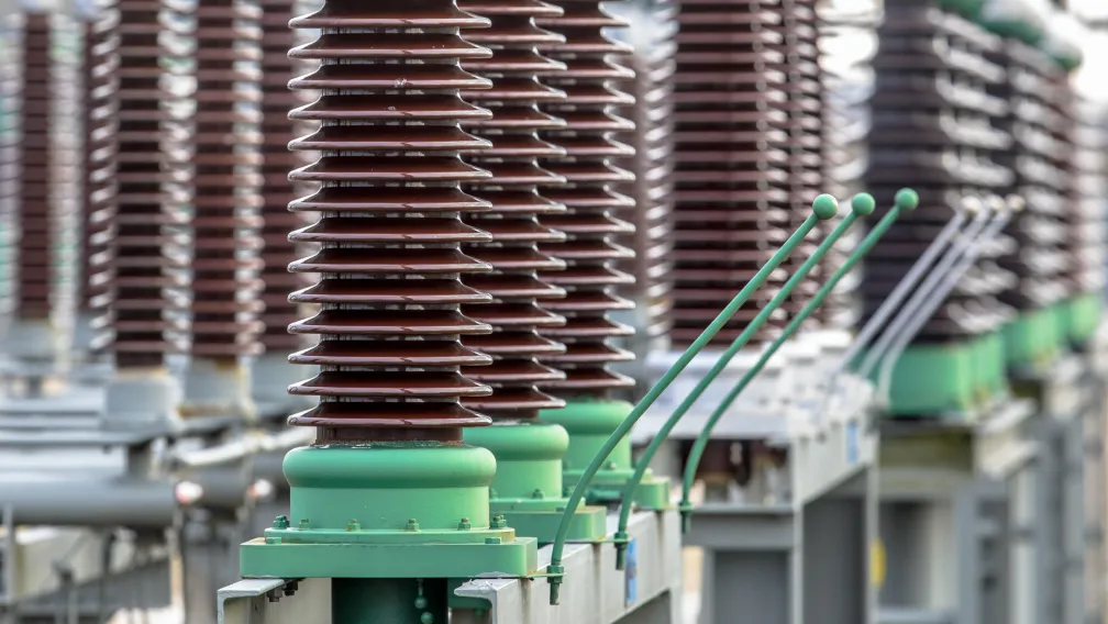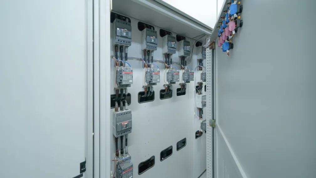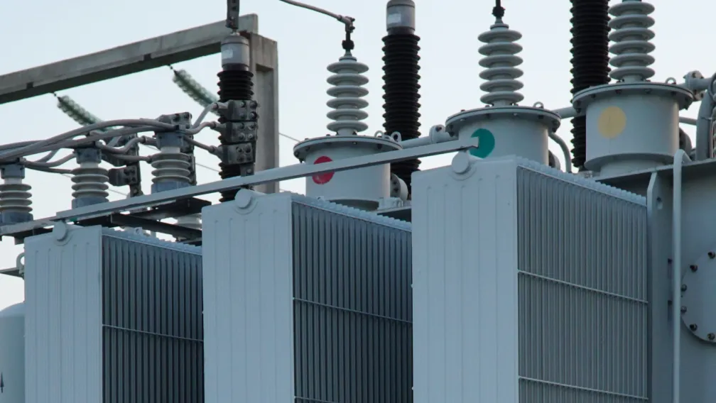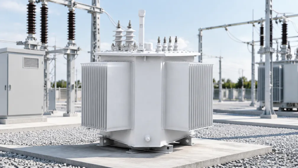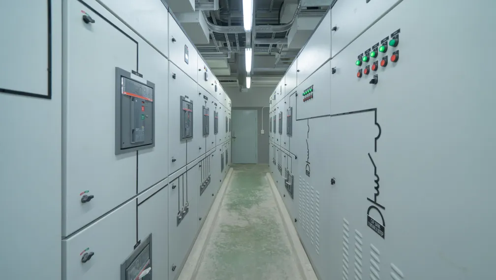


Market data through late October 2026 indicates a massive acceleration in the deployment of Battery Energy Storage Systems (BESS). Driven by the necessity to stabilize intermittent renewable generation and perform energy arbitrage, utility-scale developers are commissioning gigawatt-scale BESS facilities at unprecedented rates. However, integrating massive DC battery banks into the AC distribution grid fundamentally alters the operational stresses placed on the substation infrastructure. Standard off-the-shelf distribution equipment, designed for predictable, unidirectional utility load profiles, is experiencing accelerated degradation and premature failure when subjected to BESS operating conditions. This industry shift is forcing EPC contractors and electrical engineers to draft entirely new procurement specifications for medium voltage switchgear and step-up transformers, focusing on bi-directional fault management, severe harmonic tolerance, and aggressive thermal cycling endurance.
The Challenge of Bi-Directional Power Flow and Fault Topologies
Traditional distribution networks operate on a radial topology where power flows in a single direction: from the utility substation down to the consumer load. Consequently, standard protection relays in medium voltage switchgear are programmed to detect downstream faults. A BESS facility, however, acts as both a load (during charging) and a generator (during discharging). This bi-directional power flow completely invalidates standard overcurrent protection schemes.
In a grid-scale BESS, a short circuit can be fed from the utility grid or from the massive energy reserves of the battery racks themselves. Switchgear specified for these environments must incorporate advanced microprocessor-based relays capable of directional overcurrent and directional earth-fault protection (ANSI codes 67 and 67N). Furthermore, the switchgear must be rated to interrupt the combined prospective short-circuit current of the grid and the inverters, which often necessitates upgrading the short-time withstand current rating of the metal-clad panels from a standard 25kA to 40kA or 50kA.
Harmonic Distortion and dv/dt Stress from Power Conversion Systems (PCS)
The interface between the DC battery racks and the AC medium voltage network is the Power Conversion System (PCS). Modern PCS units utilize Insulated-Gate Bipolar Transistors (IGBTs) switching at very high frequencies to synthesize the AC waveform. While efficient, this switching generates severe high-frequency harmonic distortion and rapid voltage rise times (high dv/dt).
When these harmonics enter standard distribution transformers, they cause exponential increases in eddy current losses within the core and structural metal parts, leading to dangerous localized overheating. To survive these conditions, engineers must specify specialized energy storage transformers. These power transformers are engineered with electrostatic shields (Faraday shields) positioned between the primary and secondary windings to block high-frequency capacitive coupling. Additionally, the magnetic core and copper windings are deliberately oversized—or derated according to the K-factor or Factor K methodologies—to safely dissipate the excessive heat generated by the non-linear PCS loads.
Thermal Management Under Aggressive Duty Cycles
The thermal lifecycle of BESS electrical infrastructure is exceptionally punishing. A standard commercial transformer experiences a gradual peak in load during the day and a long cooling period at night. In contrast, grid-scale energy storage operates on aggressive duty cycles. A facility designed for solar shifting will typically charge at 100% capacity for four hours during peak irradiance, and then discharge at 100% capacity for four hours during the evening peak demand window.
This creates a thermal profile with virtually no idle cooling time. Both the dry-type transformer and the surrounding switchgear busbars operate near their maximum thermal limits for extended durations. Procurement specifications must therefore demand higher insulation classes (such as Class H 180°C for cast-resin units) and augmented forced-air cooling systems (AF/WF) to prevent the rapid degradation of dielectric materials under continuous thermal stress.
Multi-Winding Architectures for High-Density Inverters
To maximize footprint efficiency, EPCs are deploying centralized PCS architectures where multiple inverters are grouped together. Connecting multiple low-voltage inverters to the medium voltage grid using individual transformers is cost-prohibitive and consumes excessive real estate. The engineering solution is the multi-winding transformer.
BESS step-up transformers are frequently specified with one primary medium voltage winding (e.g., 35kV) and two, three, or four separate secondary low-voltage windings (e.g., 690V). Each secondary winding connects directly to a dedicated PCS unit. This complex internal geometry requires meticulous impedance matching during the manufacturing process to ensure balanced power flow and prevent circulating currents between the inverters, making the manufacturing and testing of BESS transformers significantly more complex than standard grid units.
Modular Prefabrication and Skid-Mounted Substations
The physical deployment of BESS facilities heavily favors modularity. Because energy storage sites are often located in remote areas adjacent to solar fields or wind farms, on-site civil works and electrical assembly are expensive and time-consuming. Developers are mitigating this by procuring factory-integrated compact substations.
These prefabricated skids or e-Houses contain the multi-winding step-up transformer, the medium voltage collection switchgear, and the low voltage inverter connections in a single, climate-controlled enclosure. By executing the complex internal busbar routing, control wiring, and dielectric testing in a controlled factory environment, the manufacturer delivers a "plug-and-play" node. For environments with severe space constraints or harsh climates, developers are increasingly integrating gas-insulated switchgear (GIS) into these skids to minimize the required enclosure footprint and seal the primary high-voltage components against dust, moisture, and saline pollution.
Conclusion
The proliferation of gigawatt-scale BESS in late 2026 is exposing the limitations of conventional distribution equipment. Operating environments characterized by bi-directional fault currents, high-frequency inverter harmonics, and relentless full-load thermal cycles require highly specialized electrical infrastructure. EPC contractors must transition away from standard utility specifications and mandate directional protection relays, electrostatically shielded multi-winding transformers, and factory-integrated modular architectures to ensure the long-term reliability and financial viability of energy storage assets.
Elecstellar engineers and manufactures heavy-duty medium voltage switchgear, multi-winding cast-resin energy storage transformers, and prefabricated compact substations explicitly designed to withstand the rigorous demands of utility-scale BESS integration. Contact our technical team to optimize the electrical topology and equipment specifications for your upcoming energy storage project.
-

STELLAR
Switchgear & Power Transformer ManufacturerSTELLAR designs and manufactures switchgear, transformers, and complete power distribution equipment from our China facility, serving utilities, contractors, and distributors in 50+ countries. Every technical article on this site is reviewed by our in-house engineers to ensure accuracy against IEC standards and real project practice.