search
Search

Search for equipment models, voltage specifications, or project references.


Home > LN-36 12-40.5kV SF6 Load Break Switch 630A

LN-36 12-40.5kV SF6 Load Break Switch 630A

LN-36 12-40.5kV SF6 Load Break Switch 630A

Product Description

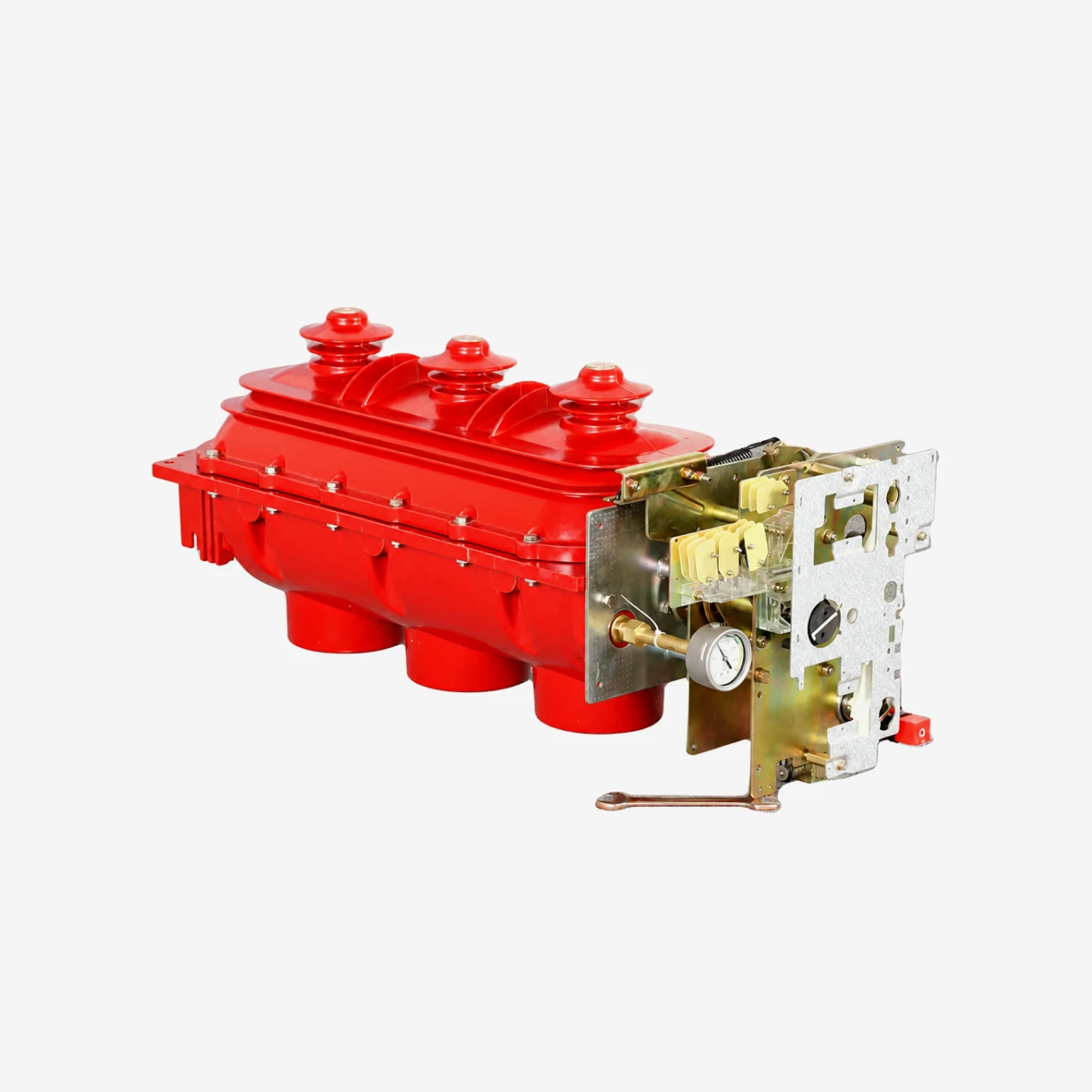
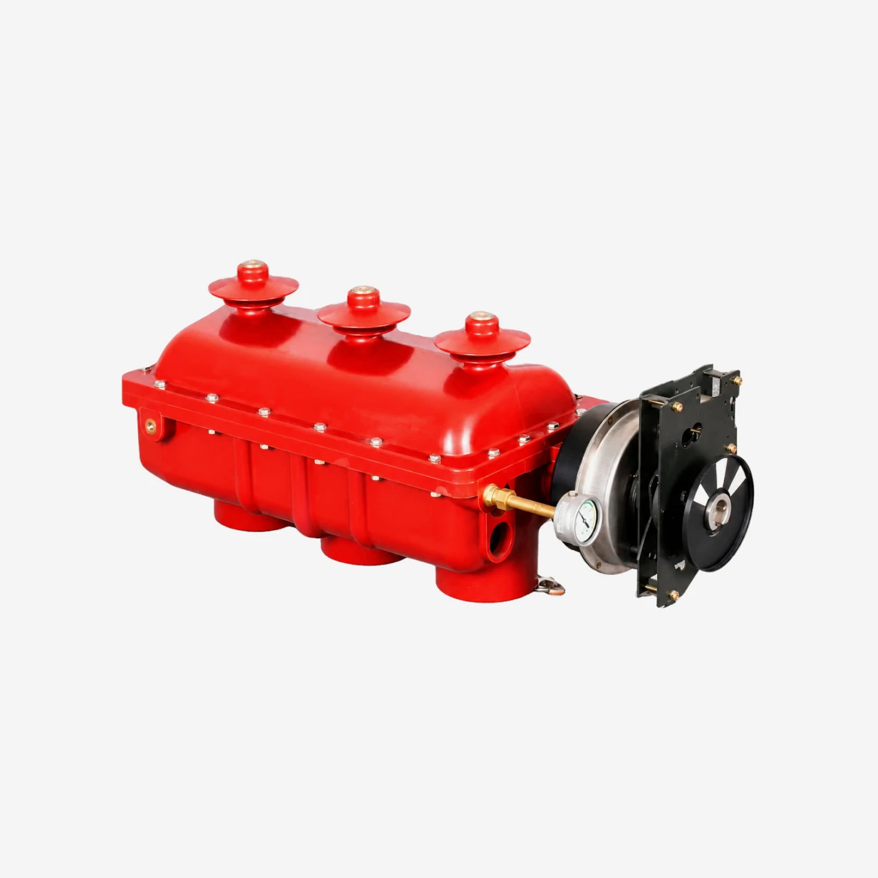
STELLAR indoor medium-voltage SF6 load break switch is a three-phase switching device built for 12kV, 24kV and 40.5kV AC distribution networks at 50Hz or 60Hz. It carries normal load currents up to 630A and provides safe isolation and earthing in compact switchgear assemblies.

The switch uses SF6 gas as both insulation and arc-quenching medium inside a sealed epoxy-resin housing. This gives it a much smaller footprint than air-insulated alternatives while maintaining full dielectric integrity. The standard configuration integrates three positions—close, open and earth—into a single sealed chamber, which reduces external wiring and simplifies panel layout.

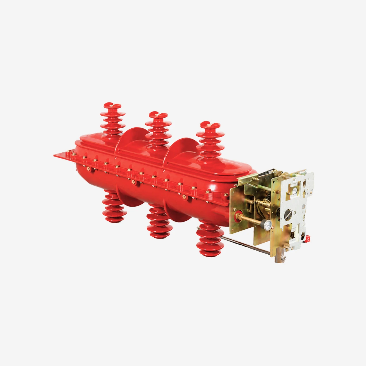
Two versions are available. The standalone load break switch covers routine switching and isolation duties with a short-circuit making capacity of 62.5kA peak at 12kV and 50kA peak at 24kV and 40.5kV. The fuse-combination version adds high-voltage current-limiting fuses to clear short-circuit faults up to the rated transfer current—1530A at 12kV, 920A at 24kV and 630A at 40.5kV—making it suitable for transformer feeder protection in ring main units and compact substations.

Operating mechanisms include a manual spring-driven handle as standard, with motorized 110V/220V AC or DC actuators available for remote control. The unit is type-tested to IEC 60265, IEC 60420 and IEC 62271-105 for insulation, temperature rise, short-time withstand and mechanical endurance.

Typical applications include ring main units, cable branch boxes, prefabricated substations, industrial distribution panels and utility secondary substations where space is limited and reliable load control is required.

Technial Parameters

TECHNICAL PARAMETERSUNITS12 kV24 kV40.5 kV
Rated voltagekV122440.5
Rated currentA630630630
Rated power frequencyHz50 / 6050 / 6050 / 60
Short-circuit making capacity (peak)kA62.55050
Peak withstand currentkA62.55050
Short-time withstand current (1 s)kA25
Short-time withstand current (2 s)kA2020
Max. breaking capacity with fuses (IEC 62271-105)A1530920630
Mainly active load breaking capacityA630630630
Cable charging currentA630630630
Power frequency withstand voltage (to earth / between poles)kV425595
Power frequency withstand voltage (across isolating distance)kV4570120
Lightning impulse withstand voltage (to earth / between poles)kV75125190
Lightning impulse withstand voltage (across isolating distance)kV85145220
Mechanism endurancecycles100010001000
SF6 gas rated pressure (gauge, 20°C)MPa0.04 – 0.050.04 – 0.050.04 – 0.05
Annual SF6 gas leakage rate%≤ 0.1≤ 0.1≤ 0.1
Operating mechanism/Manual / MotorizedManual / MotorizedManual / Motorized
Ambient temperature range°C-25 to +40-25 to +40-25 to +40
Standard compliance/IEC 60265, IEC 60420, IEC 62271-105, GB 3804, GB 16926

Product Details

Three-Position Integration in One Sealed Chamber

Most conventional switchgear needs separate isolators and earthing switches to achieve safe isolation. This unit combines closing, opening and earthing functions inside a single SF6-filled epoxy housing. The moving contact assembly travels through clearly defined positions with mechanical interlocks that prevent closing onto an earthed circuit or earthing a live line. The result is fewer components, less panel depth and lower wiring complexity.

SF6 Gas Insulation and Arc Quenching

SF6 has dielectric strength roughly three times that of air at atmospheric pressure. Inside the sealed tank, the gas extinguishes arcs by capturing free electrons and cooling the plasma column within milliseconds. Because the contacts operate inside a closed environment, oxidation and humidity have no effect on contact surfaces. The pressure remains stable over decades under normal operation, with annual leakage held below 0.1%.

Epoxy-Resin Sealed Housing

The switch body is cast from high-strength epoxy resin using APG pressure-gelation. This creates a hermetic barrier that keeps moisture, dust and corrosive gases away from live parts. The housing is rated for internal arc containment and includes a pressure-relief diaphragm on the rear or top face. If an internal fault occurs, expanding gas vents through the relief path rather than stressing the main enclosure seals.

Spring Operating Mechanism

The manual mechanism uses a single disc spring for energy storage. A quarter-turn of the handle charges the spring; continued rotation releases it to drive the contact system through its full travel. The stored-energy design means the operator applies the same light force regardless of switching duty. For automated networks, a motorized actuator bolts directly onto the manual mechanism without panel modifications. Motor options cover DC 48V, AC/DC 110V and AC/DC 220V.

Fuse-Combination Protection

When fitted with high-voltage current-limiting fuses, the switch becomes a combined protective device. The fuses carry normal load current and clear short-circuit faults inside their rated breaking range. A fuse striker mechanically trips the three-phase load switch whenever any fuse blows, ensuring full isolation of the faulted transformer or cable. The rated transfer current—1530A at 12kV, 920A at 24kV and 630A at 40.5kV—defines the upper limit where the fuse takes over from the switch.

Application Scope

This load break switch is intended for indoor installations in ring main units, cable distribution boxes, compact substations and factory distribution boards. It controls power flow in urban cable networks, isolates transformers for maintenance, and sections industrial feeders. The compact width and fixed mounting suit both new switchgear lines and retrofit projects where existing floor space is constrained.

FAQs

What voltage and current ratings does this SF6 load break switch cover?

The switch covers three voltage tiers: 12kV, 24kV and 40.5kV. Rated current is 630A at all voltage levels. Short-circuit making current is 62.5kA peak at 12kV and 50kA peak at 24kV and 40.5kV. Short-time withstand current is 25kA/1s at 12kV and 20kA/2s at 24kV and 40.5kV. These ratings match standard medium-voltage distribution requirements in most regions.

How does the three-position close-open-earth design improve safety?

The three-position design places closing, opening and earthing contacts inside one sealed chamber with mechanical interlocks. This prevents the operator from closing the main circuit while the earthing position is engaged, and from moving to earth while the line is energised. Fewer separate devices means fewer failure points and less panel depth.

What is the difference between a standalone load switch and a fuse-combination unit?

A standalone load break switch switches and isolates normal load current up to 630A. The fuse-combination version adds high-voltage current-limiting fuses that clear short-circuit faults. When a fuse blows, its striker trips all three phases of the load switch automatically. The combination unit is used for transformer feeder protection where fault levels exceed the switch's own breaking capability.

Can this switch interrupt short-circuit fault current on its own?

No. A load break switch is designed to make, carry and break normal load current. It can close onto a short circuit safely, but it cannot break fault current. Short-circuit protection must be provided by upstream circuit breakers or by the integrated fuses in a combination unit. Attempting to open the switch under fault conditions would damage the contacts and endanger personnel.

What maintenance does a sealed SF6 load break switch require?

Very little under normal conditions. The sealed SF6 system is maintenance-free for the electrical life of the unit. Periodic checks should include visual inspection of the housing, verification of gas pressure via the optional gauge, and lubrication of the external operating mechanism every few years. No gas refilling is needed if the annual leakage rate stays below the 0.1% design limit.