Current-Limiting Interruption Principle
Unlike expulsion fuses that wait for a natural current zero, a current limiting fuse forces the arc to extinguish inside the first half-cycle. The specially profiled silver ribbon contains narrow notched sections that heat and vaporize almost simultaneously when a severe fault occurs. Multiple series arcs form instantly, and the intense thermal energy melts the surrounding high-purity quartz sand. The molten sand chemically fuses with vaporized silver to create a solid, highly resistive fulgurite that introduces megohm-level resistance into the circuit. The fault current waveform peaks prematurely and collapses to zero before it can reach the prospective peak value.
This process typically completes within 8.33 ms on 60 Hz systems or 10 ms on 50 Hz systems. By cutting off the current early, the fuse drastically reduces let-through energy (I²t), which is the primary cause of thermal and mechanical damage to transformer windings during short-circuit events.
High Breaking Capacity with Low Power Loss
The series is rated for breaking capacities up to 50kA, covering the fault levels found in most medium-voltage distribution networks. Despite this high interrupting capability, the fuse links are designed for low continuous power loss. Stable resistance values and optimized element geometry keep temperature rise within IEC limits, even when installed in fully enclosed switchgear or compact ring main units where ventilation is restricted. Low power loss also reduces thermal fatigue during repeated inrush events, helping prevent nuisance operation over the service life of the fuse.
Structural Design and Material Specification
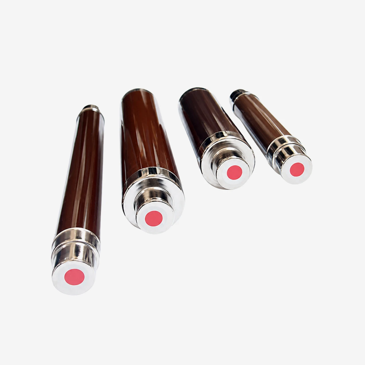
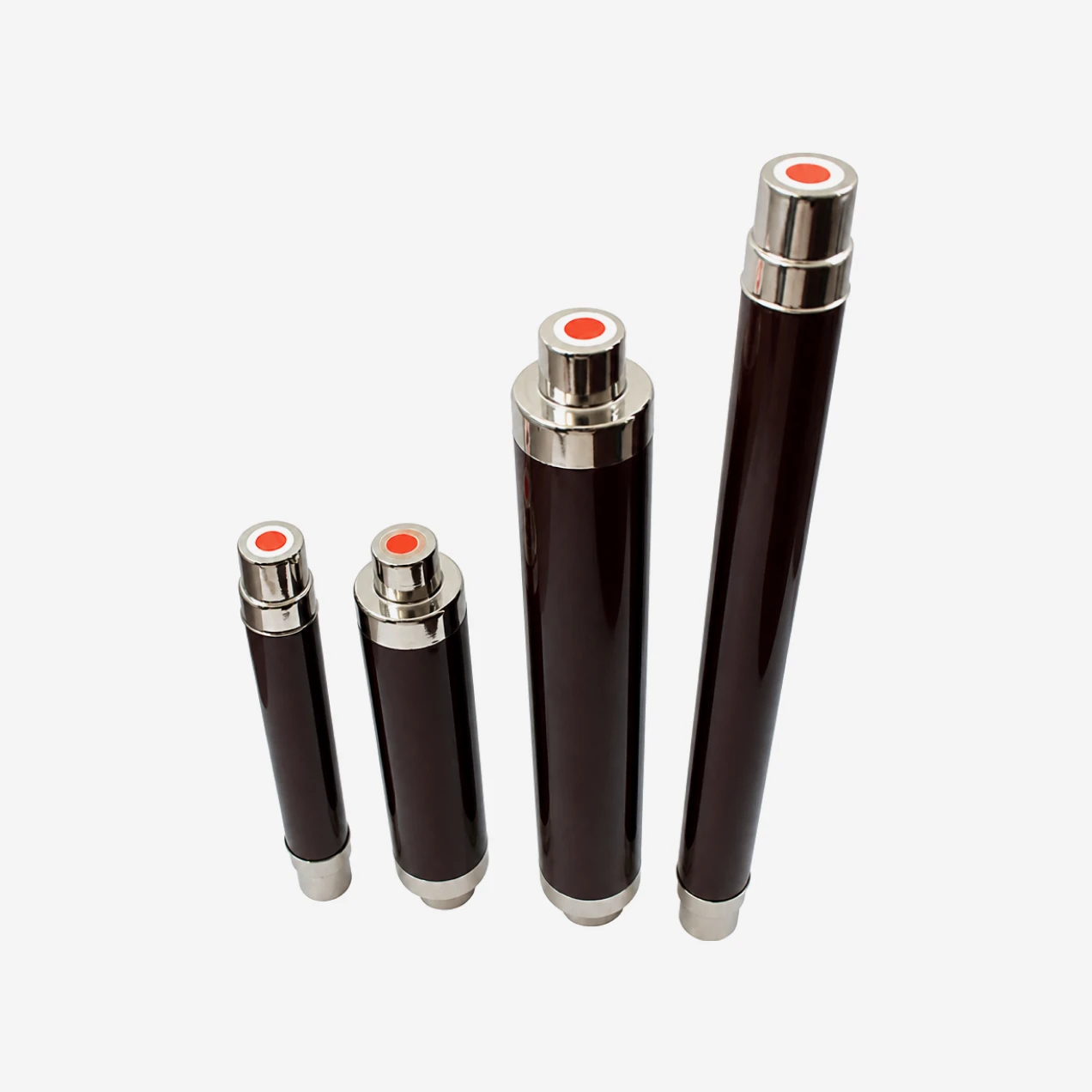
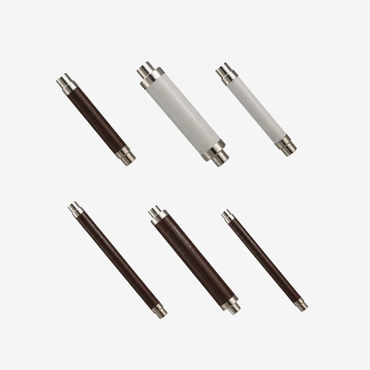
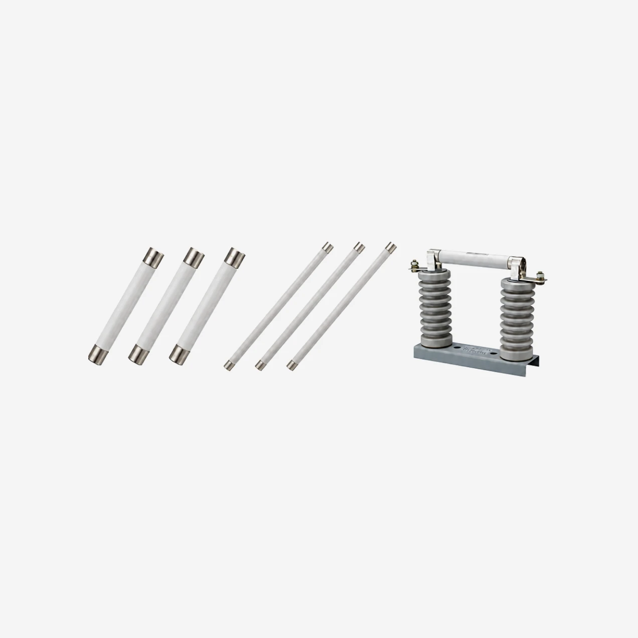
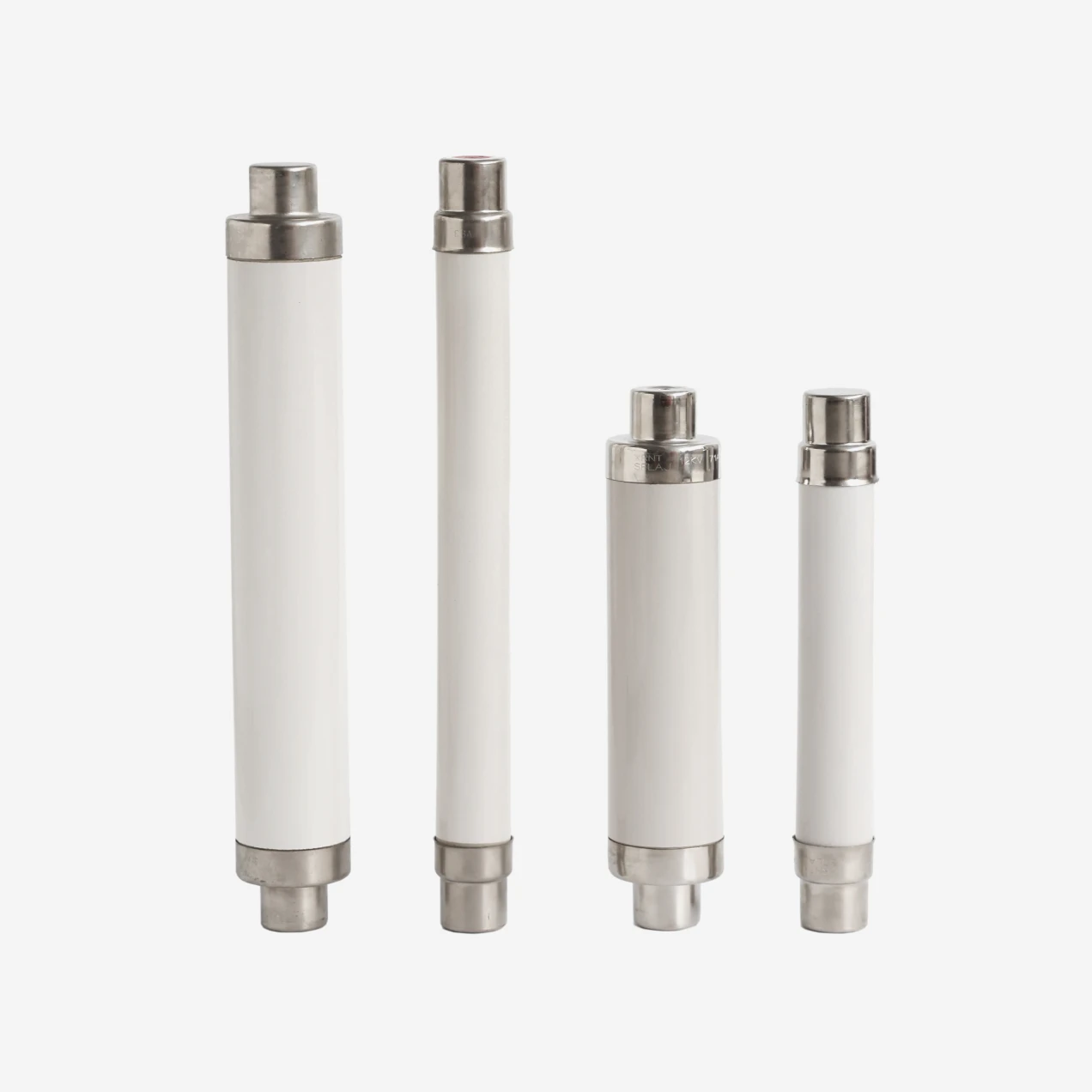
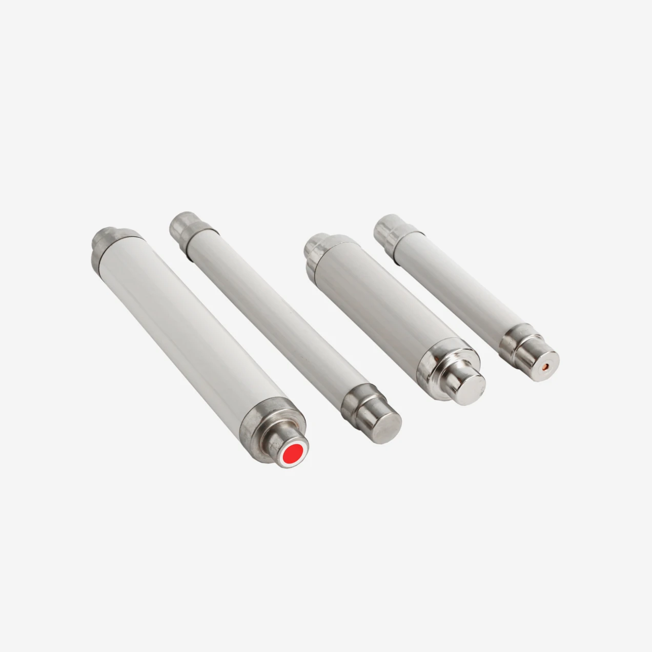
The fuse tube is manufactured from high-density alumina ceramic capable of withstanding internal pressures generated during high-current interruption. Both ends are sealed with nickel-plated copper caps that maintain reliable electrical contact and resist corrosion in humid or contaminated environments. The internal fuse element is a precision-wound silver-alloy ribbon supported on a high-temperature ceramic core. Grain-size-controlled quartz sand (≥99% SiO₂) fills the tube under vibration-compacted conditions to ensure consistent arc-quenching performance across the entire current range.
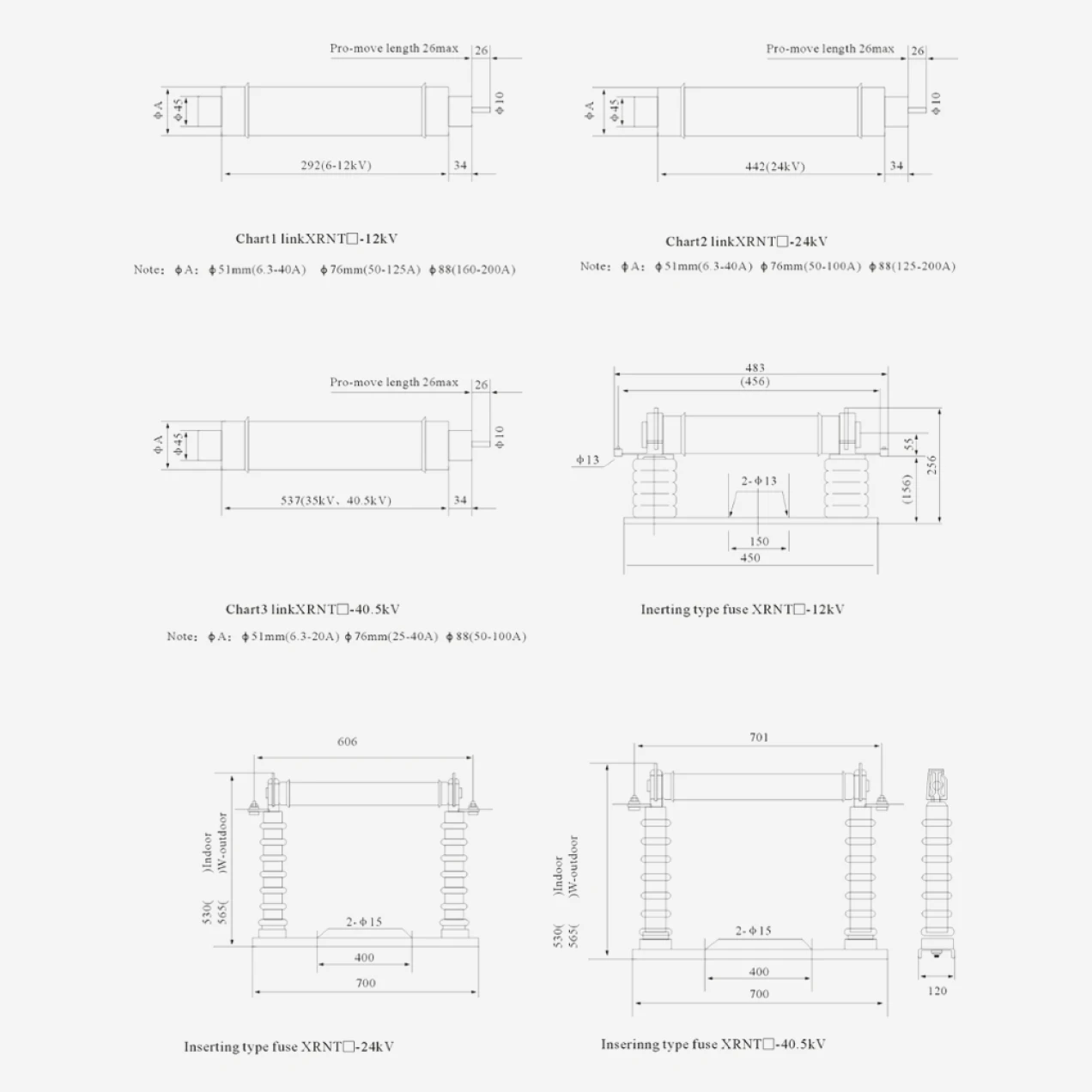
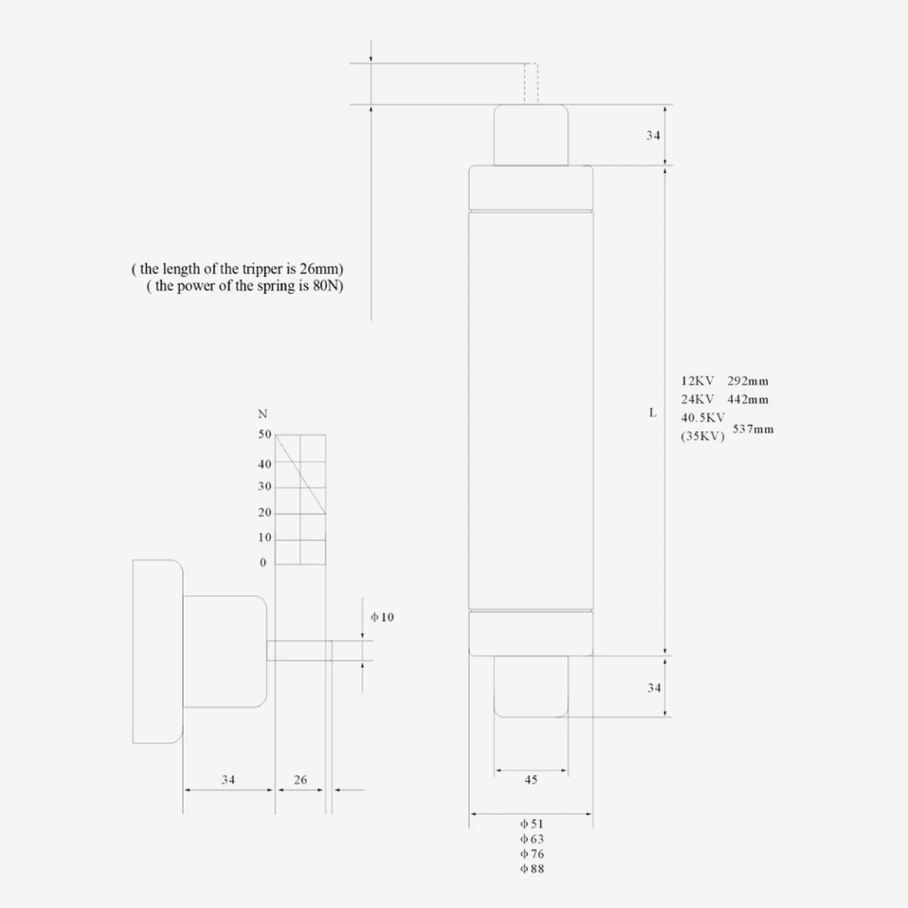
Dimensional compliance with DIN 43625 ensures direct interchangeability with standard fuse bases, switch-fuse combinations, and unit fuse holders from major switchgear manufacturers. Tube diameters range from 51mm for lower current ratings to 88mm for 160A–200A links; lengths correspond to voltage class (292mm for 7.2kV, 442mm for 12kV/24kV, and up to 537mm for 36kV/40.5kV).
Striker and Indication Systems
Optional striker pins are available for applications requiring remote fault indication or automatic tripping of three-phase switch mechanisms. When the fuse element melts, a parallel tungsten wire ignites a small powder charge that drives the striker pin outward with sufficient energy to actuate microswitches or mechanical latches. Striker output energy conforms to IEC 60282-1 (medium, 1–3J) or DIN 43625 (2–5J) specifications, depending on the tripping force required by the associated switchgear. This feature is essential for switch-fuse combinations where single-phase operation must trigger full three-phase isolation to prevent sustained unbalanced loads.
Transformer Protection Coordination
Proper fuse selection for transformer circuits follows the criteria outlined in IEC/TR 60787. The rated current must be high enough to withstand magnetizing inrush currents—typically 10 to 12 times full-load current for approximately 0.1 seconds during energization—yet low enough to clear secondary-side bolted faults before transformer damage occurs. The fuse must also coordinate with downstream low-voltage protection so that minor overloads are cleared by the secondary-side device while the high-voltage backup fuse handles catastrophic short circuits. STELLAR provides time-current characteristic curves and coordination tables to support correct selection across standard transformer kVA ratings from 50kVA to 2500kVA.
Standards, Testing and Quality Assurance
Every production batch undergoes routine testing that includes visual inspection, dimensional verification, cold resistance measurement, insulation resistance checks, and dielectric withstand tests. Type tests covering breaking capacity, temperature rise, time-current characteristics, and impulse voltage withstand are performed on representative samples in accordance with IEC 60282-1. All fuse links are marked with rated voltage, current, breaking capacity, and manufacturing trace codes to ensure long-term identification in the field.