search
Search

Search for equipment models, voltage specifications, or project references.


Home > SF6XGN-24 Gas-Insulated Medium Voltage Switchgear (AFLR 20kA/0.5s)

SF6XGN-24 Gas-Insulated Medium Voltage Switchgear (AFLR 20kA/0.5s)

SF6XGN-24 Gas-Insulated Medium Voltage Switchgear (AFLR 20kA/0.5s)

Product Description:
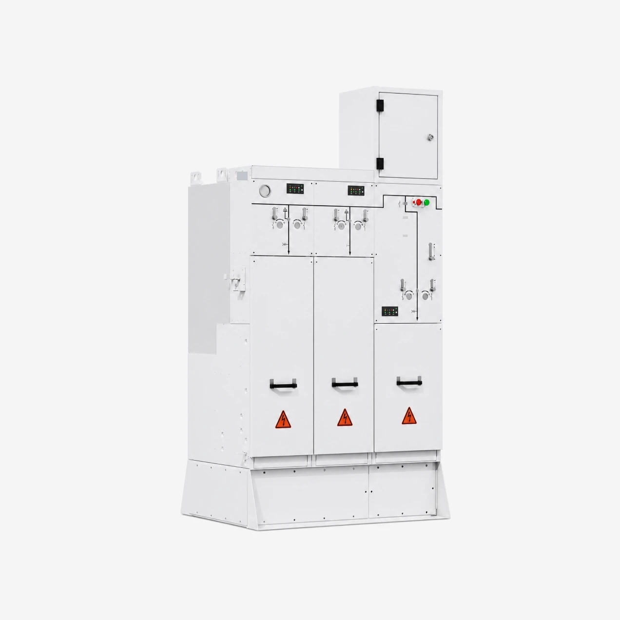
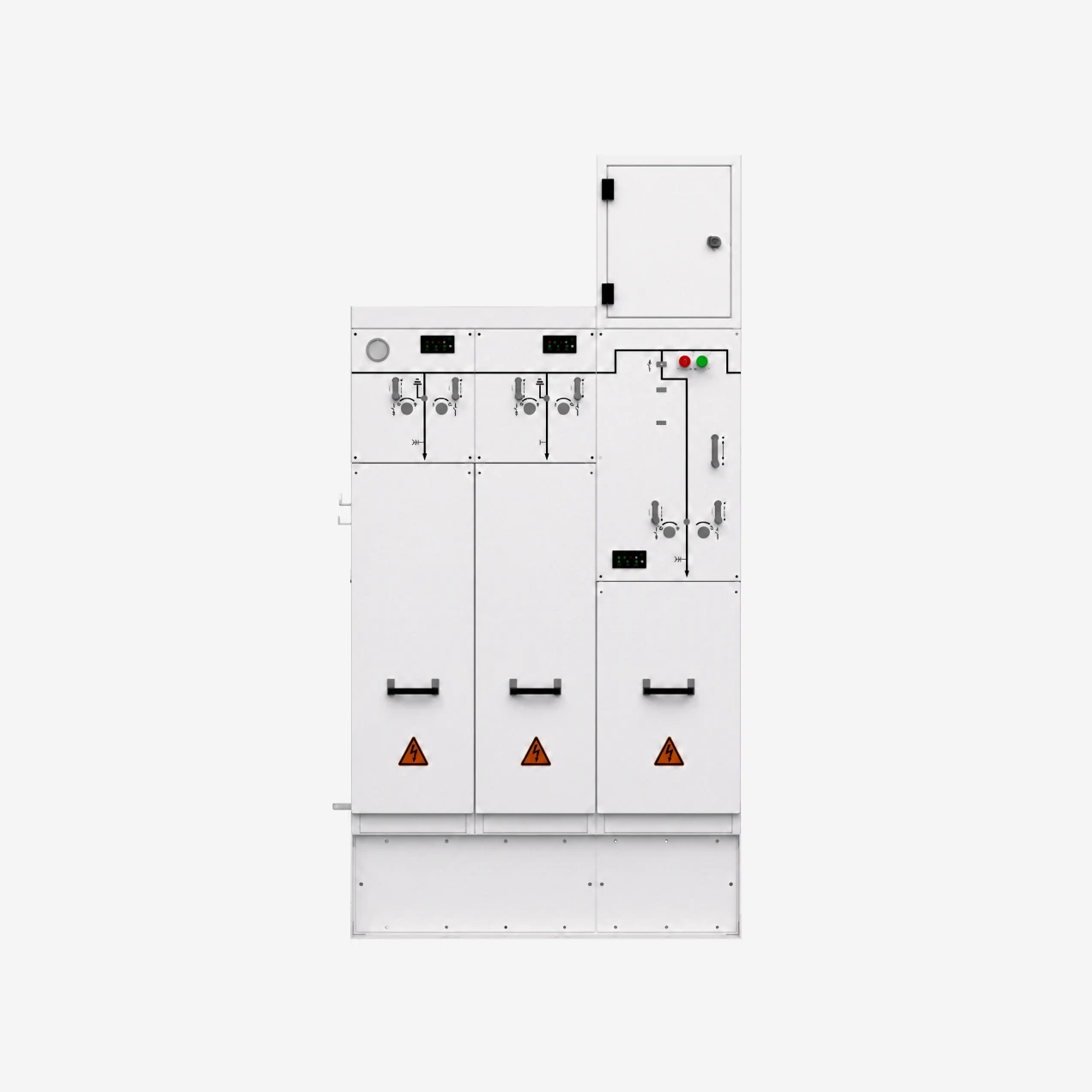
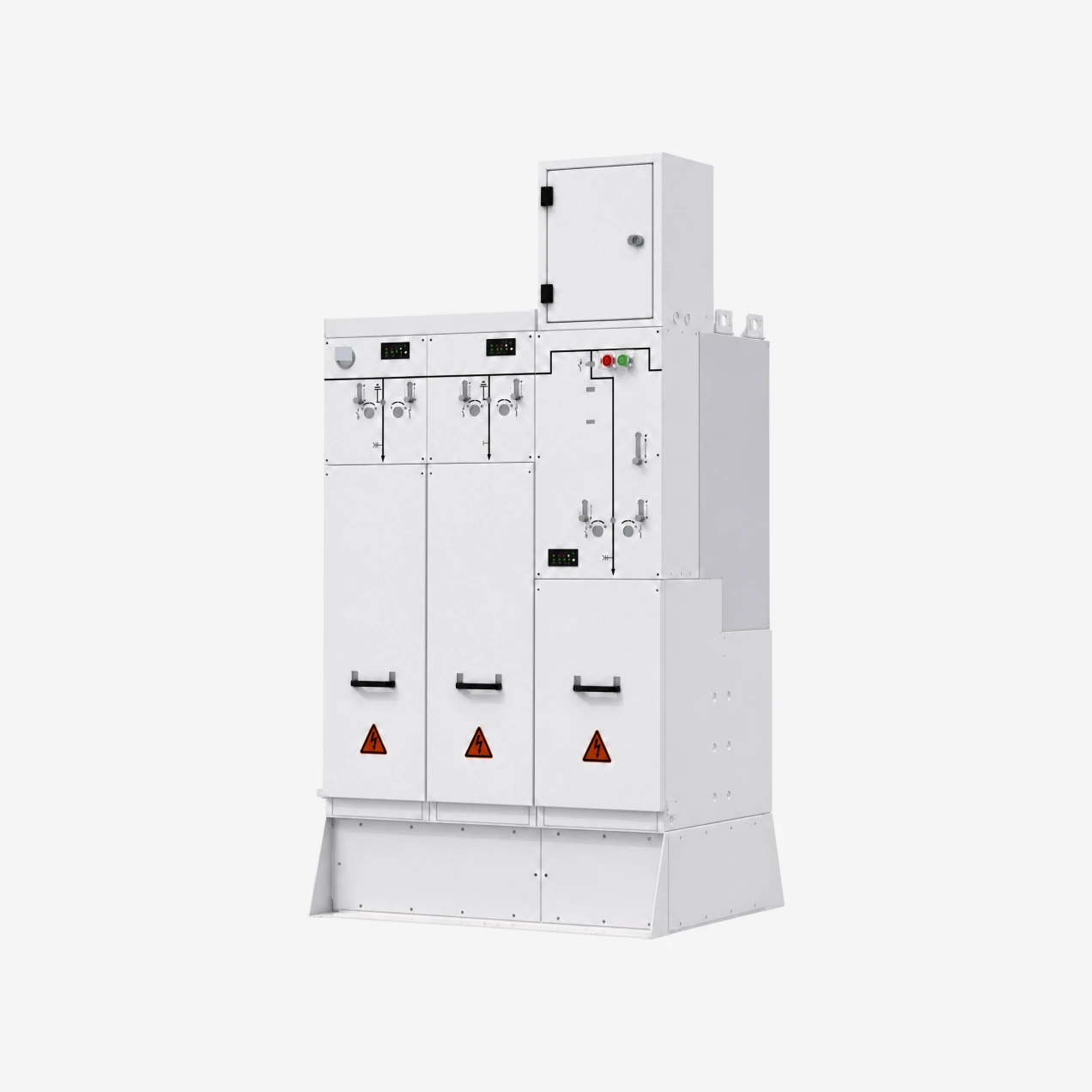
STELLAR 24kV gas-insulated medium voltage switchgear is a new-generation SF6 fully-insulated ring main unit (RMU) engineered for the 20-24kV distribution layer. This voltage tier sits above the widely-deployed 10-12kV distribution level but below the 35-40.5kV sub-transmission tier, so it is the natural fit for distributed generation interconnection, city networks migrating from 10kV to 20kV, rail electrification auxiliary distribution and modernised industrial substations. All live components and primary equipment are sealed inside a 3mm 304 stainless steel gas tank, delivering maintenance-free operation, high reliability and safe operator interaction with a compact footprint that fits inside a distribution kiosk, a prefabricated substation or a building electrical room.
Modular architecture allows the C-unit (cable / ring switch), F-unit (fuse combination) and V-unit (vacuum breaker) to be combined per single-line diagram. Extension busbars are fully-insulated and screened so line-ups can be extended safely in space-constrained installations. The load-break switch – fuse combination unit is rated at 24kV / 1400A transfer current, wide enough to cover the full range of distribution transformer ratings typically encountered at the 20-24kV level.
Available Configurations
• Rated voltage: 24kV
• Rated frequency: 50 Hz
• Rated current: C-unit 630A / F-unit 125A / V-unit 630A
• Power frequency withstand: 65 / 79 (isolation gap) kV
• Lightning impulse withstand: 125 / 145 (isolation gap) kV
• Internal arc classification: AFLR 20kA / 0.5s
• Enclosure IP41; gas tank IP67; complete switching station IP54 with IK10 impact rating
• Annual gas leakage rate: ≤ 0.01%
• Load-break switch mechanical endurance: 5000 operations; vacuum circuit breaker: 10000 operations
• Load-break switch – fuse combination transfer current: 24kV, 1400A
• 3mm 304 stainless steel gas tank, laser-welded on TRUMPF systems
• Automatic helium leak detection with SEILER equipment during production
• Modular C / F / V unit combinations per SLD
Ordering Information
Send us your single-line diagram, unit combination requirement, incoming direction, installation site type (distribution kiosk / DG interconnection point / prefab substation / rail auxiliary substation) and target IP rating. Our engineering team will return a customised panel layout and general arrangement drawing for your approval before production.

Technial Parameters

TECHNICAL PARAMETERS (BASIC DATA)UNITSVALUE / PARAMETERS
Rated voltagekV24
Rated frequencyHz50
Rated currentAC-unit: 630 F-unit: 125 V-unit: 630
Rated power frequency withstand voltagekV65 / 79 (isolation gap)
Rated lightning impulse withstand voltagekV125 / 145 (isolation gap)
Mechanical enduranceoperationsC-unit: 5000 F-unit: 5000 V-unit: 10000
Rated short-circuit breaking currentkAF-unit: 31.5 V-unit: 20
Rated short-circuit making currentkAC-unit: 50 F-unit: 80 V-unit: 50
Rated transfer currentAF-unit: 1400
Main circuit rated short-time withstand current (4s)kA20 / 25
Main circuit rated peak withstand currentkA50 / 63
Internal arc classification/AFLR, 20kA, 0.5s
Rated operating pressure (20°C, gauge)MPa0.03
Minimum operating pressure (20°C, gauge)MPa0.02
Enclosure protection class/IP41
Gas tank protection class/IP67
Switching station protection class/IP54
Switching station impact protection class/IK10
Annual gas leakage rate/≤ 0.01%

Product Details

Sealed Stainless Steel Gas Tank for 20-24kV Distribution

The 20-24kV distribution level occupies a specific niche in the medium voltage landscape. It sits above the widely-deployed 10-12kV city distribution level and below the 35-40.5kV sub-transmission tier. That makes it the practical choice for three growing use cases: interconnection points for distributed generation plants (wind, PV, storage), city distribution networks migrating from 10kV to 20kV to improve loss and capacity, and rail electrification auxiliary distribution feeding the 25kV traction system. On this platform, all primary live parts are sealed inside a 3mm 304 stainless steel gas tank, so the RMU can be installed and forgotten — the tank interior is not accessible in service and does not need to be.

Compact RMU Footprint for Distribution Substations

The physical footprint is engineered for space-constrained installations typical at the 20-24kV level: distribution kiosks alongside DG plants, container substations at DG interconnection points, prefabricated substations sited at the edge of industrial parks, and building electrical rooms in mixed-use developments. The compact tank layout leaves room for cable termination access and door swing in installations that would not accommodate an air-insulated cabinet of equivalent rating. Modular C / F / V unit combinations mean the exact feeder mix required by the single-line diagram is delivered without oversized cabinet volume.

3mm 304 Stainless Steel Tank, Laser-Welded on TRUMPF Systems

The gas tank is built from 3mm 304 stainless steel plate and welded on 3D five-axis laser welding systems imported from TRUMPF (Germany). Laser welding produces a narrow uniform seam with much lower heat-affected zone distortion than conventional MIG or TIG welding, which translates directly into better long-term gas tightness. The finished tank has a smoother external appearance without post-grinding — a real detail on rooftop or public-facing installations where the switching station is visible.

Verified ≤0.01% Annual Gas Leakage — 30-Year Service Life

Every finished tank is leak-tested on a SEILER (Germany) automatic helium leak detection line. Helium mass spectrometry can detect leak paths several orders of magnitude smaller than pressure-decay methods, so the ≤0.01% per year annual leakage rating is a verified factory number, not an extrapolation. The tank normal service life is more than 30 years, meaning an RMU installed today at a wind or PV interconnection point should carry through the full generation asset's design life without gas top-up.

Fully-Insulated Solid Extension Busbar

Extension busbars use fully-insulated screened solid busbar construction. Every conductive surface is covered by a bonded insulation layer with an outer earthed screen, so the busbar surface can be safely handled during connection work and there is no exposed live metal even when a tank is open. This matters on distributed generation projects where the RMU sits inside a container substation and the operator is close to the equipment during commissioning and future extension work.

24kV, 1400A Load-Break Switch – Fuse Combination Transfer Current

The load-break switch – fuse combination unit at 24kV is rated at a transfer current of 1400A. Transfer current is the current level up to which the load-break switch can safely commutate the feeder onto the fuse element without arc restrike, so a high transfer current widens the range of feeder loads that can be protected through the fuse combination. At 24kV, a 1400A rating covers all practical distribution transformer ratings on a 20-24kV feeder — including the larger transformer sizes seen at industrial and DG interconnection substations.

AFLR 20kA / 0.5s Internal Arc with IP54 / IK10 Switching Station Protection

Internal arc classification is AFLR 20kA / 0.5s — accessibility on Front (A), Lateral (L) and Rear (R) verified for a 20kA arc fault sustained for 0.5 seconds. At the switching-station level (the complete installation including cabinet and mounting enclosure), protection reaches IP54 against dust and water ingress, with IK10 mechanical impact protection. This is the combination expected of a container substation at a DG interconnection point or a compact rooftop switching station exposed to weather and impact.

Applications: Distributed Generation, Urban Network Upgrade, Rail Auxiliary

Three application segments drive most demand for a 24kV RMU today. First, distributed generation interconnection: wind farms, PV plants and battery storage sites terminate the medium voltage collector system into an RMU at the plant boundary, and 24kV is a common collection-network voltage. Second, city distribution networks migrating from 10-12kV to 20kV, where existing feeders are re-insulated for higher voltage to raise capacity without laying new cable — the RMU is the switching device at each substation on the upgraded network. Third, rail electrification auxiliary distribution feeding station lighting, signalling, HVAC and depot loads from the 25kV traction supply through a step-down to 20-24kV. The compact sealed RMU suits all three because the installation environment is invariably confined and long-term maintenance access is limited.

FAQs

What is a 24kV gas-insulated RMU and where is it typically deployed?

A 24kV gas-insulated ring main unit (RMU) is a compact switchgear assembly used at the 20-24kV distribution layer — the tier between the 10-12kV city distribution level and the 35-40.5kV sub-transmission tier. Live parts are sealed inside a gas tank, so the assembly can sit in confined spaces without ventilation or maintenance access. Typical installations include distributed generation interconnection substations (wind, PV, storage), city networks migrating from 10kV to 20kV, rail electrification auxiliary distribution, prefabricated substations at industrial park edges and building main distribution rooms.

How does the sealed gas tank guarantee maintenance-free operation for 30 years?

All primary live parts are sealed inside a 3mm 304 stainless steel tank, laser-welded on TRUMPF systems. Every tank is helium leak-tested on SEILER automated equipment before shipment, and the verified annual leakage rate is ≤0.01%. The tank normal service life is more than 30 years, so under standard operating conditions no gas top-up is required across the life of the installation. Routine cabinet cleaning and internal insulation inspection cycles typical of air-insulated switchgear are eliminated.

What is the 24kV / 1400A transfer current and why does it matter for distribution engineers?

Transfer current is the current level up to which the load-break switch can safely commutate the feeder load onto the fuse element without arc restrike. At 24kV, the load-break switch – fuse combination unit handles 1400A transfer current — high enough to cover all practical distribution transformer ratings on a 20-24kV feeder, including the larger transformer sizes typical at industrial substations and DG interconnection points. For distribution engineers this means the fuse combination unit is a valid protection choice across the full feeder-load range at this voltage tier.

Can this switchgear serve as the interconnection point for a wind, PV or battery storage plant?

Yes — DG interconnection is one of the primary use cases. Wind farms, PV plants and battery storage sites collect at a medium voltage collector network (24kV is a very common collection voltage) and terminate that network into an RMU at the plant boundary before stepping up to the transmission voltage. The compact sealed RMU suits interconnection substations because the equipment room is typically a container or prefab structure with limited access, and the operator's asset management model relies on maintenance-free equipment for the full 25-30 year plant life.

What internal arc and impact protection does the panel provide?

Internal arc classification is AFLR 20kA / 0.5s, with accessibility verified on Front, Lateral and Rear sides. At the complete switching-station level, protection reaches IP54 against dust and water ingress, with IK10 mechanical impact protection. This combination is what container substations and compact rooftop switching stations need to sit outdoors, exposed to weather and possible impact from vehicles or public interaction.

What input do you need for a customised offer?

Send us your single-line diagram with the required unit combination (C / F / V mix), incoming direction, the installation site type (DG interconnection point / urban distribution substation / rail auxiliary / prefabricated substation), the target IP rating and any specific certification requirements for the destination market. Our engineers return a panel layout, general arrangement drawing and section view for your approval before we release the order to production.