search
Search

Search for equipment models, voltage specifications, or project references.


Home > FN5 12/24kV Indoor Load Break Switch and Fuse Combination 400A/630A

FN5 12/24kV Indoor Load Break Switch and Fuse Combination 400A/630A

FN5 12/24kV Indoor Load Break Switch and Fuse Combination 400A/630A

Product Description

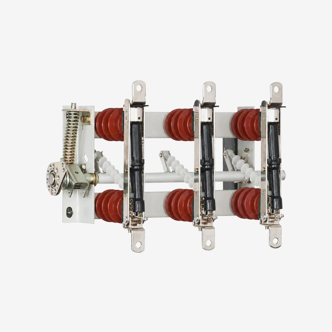
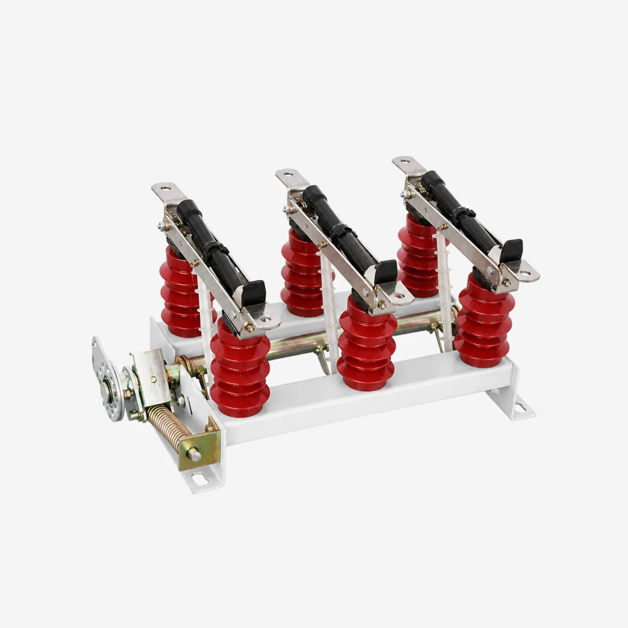
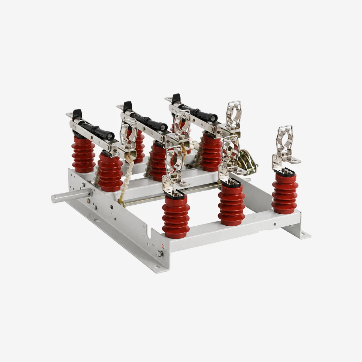
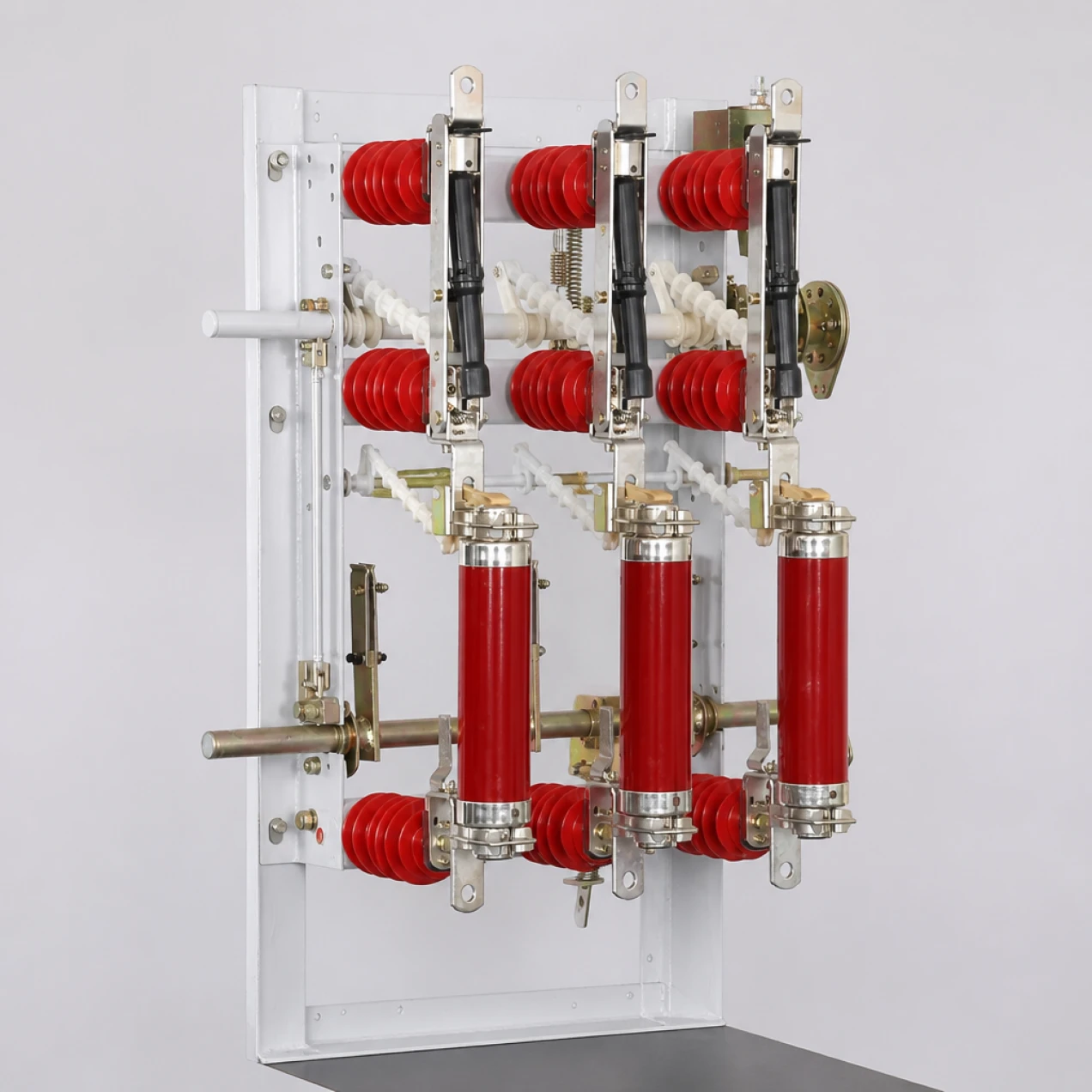
STELLAR 12/24kV indoor high-voltage load break switch and fuse combination apparatus is a three-phase switching device for 50Hz or 60Hz medium-voltage distribution networks. It covers two voltage tiers—12kV and 24kV—with continuous current ratings of 400A or 630A.

The standard unit is a manual air-type load break switch using compressed-air arc quenching. A visible isolation gap opens when the switch is in the off position, giving maintenance crews direct visual confirmation that the circuit is isolated. The conductive path is built from high-conductivity copper with silver-plated contact surfaces to keep temperature rise within limits.

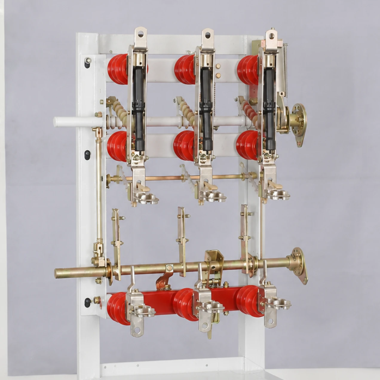
Optional factory-fitted modules expand the function without increasing the footprint. A high-voltage current-limiting fuse assembly adds short-circuit protection up to 1600A at 12kV or 900A at 24kV. An earthing switch provides safe grounding of the load side for maintenance. A mechanical tripping device automatically opens all three phases when any fuse blows, ensuring the faulted transformer or cable is fully isolated.

Operating mechanisms include a spring-assisted manual handle as standard, with motorized actuators available for remote control. The unit is type-tested to IEC 62271-105 for load switch-fuse combinations and GB 3804 for insulation, temperature rise, short-time withstand and mechanical endurance.

Typical installations include 10kV/12kV and 20kV/24kV indoor transformer substations, cable distribution boxes, ring main units and factory switchgear lines where compact size and reliable load control are required.

Technial Parameters

TECHNICAL PARAMETERSUNITS12 kV (400 A)12 kV (630 A)24 kV (630 A)
Rated voltagekV121224
Rated currentA400630630
Rated frequencyHz50 / 6050 / 6050 / 60
Rated short-circuit making current (peak)kA31.55063
Rated peak withstand currentkA31.55063
Rated short-time withstand currentkA12.5 (4 s)25 (1 s)25 (1 s)
Rated short-time withstand current (alternate)kA20 (2 s)14 (3 s)
Max. breaking capacity with fuses (IEC 62271-105)A1600900
Max. fuse current (XRNT type)A200200
Mainly active load breaking capacityA400630630
Cable charging breaking currentA101010
1-min power frequency withstand voltage (to earth / between poles)kV424255
1-min power frequency withstand voltage (across isolating distance)kV484870
Lightning impulse withstand voltage (to earth / between poles)kV7575125
Lightning impulse withstand voltage (across isolating distance)kV8585145
Mechanical endurancecycles100010002000
Operating mechanism/Manual / MotorizedManual / MotorizedManual / Motorized
Ambient temperature range°C-25 to +40-25 to +40-25 to +40
Max. installation altitudem100010001000
Standard compliance/IEC 62271-105, IEC 60265, GB 3804

Product Details

12/24kV Dual-Voltage Platform

The switch is built on a common frame that accepts either 12kV or 24kV insulation components. At 12kV the unit withstands 42kV power frequency and 75kV lightning impulse across the main gaps. At 24kV these ratings rise to 55kV and 125kV respectively. The same operating mechanism and mounting pattern are used for both voltages, which simplifies inventory and panel design for switchgear builders who serve multiple grid standards.

Compressed-Air Arc Quenching with Visible Isolation Gap

When the contacts separate, the moving contact draws the arc through a compressed-air arc-extinguishing tube. The air flow cools and stretches the plasma column until it cannot sustain itself. This method is simple, reliable and requires no sealed gas or vacuum bottles. After the arc is extinguished, the moving contact drops away from the fixed contact to create a clear, visible air gap that meets safety standards for maintenance access.

Fuse-Combination Short-Circuit Protection

In the fuse-combination version, high-voltage current-limiting fuses mount directly above the switch body. The fuses carry normal load current and clear short-circuit faults inside their rated breaking range. At 12kV the combined breaking capacity reaches 1600A; at 24kV it is 900A. A fuse striker mechanically trips the three-phase load switch whenever any fuse blows, ensuring full isolation of the faulted circuit. This integration removes the need for separate protective relays and circuit breakers in small distribution substations.

Integrated Earthing and Tripping Options

The earthing switch option adds a grounded blade on the load side that closes after the main contacts open. This gives maintenance crews a physical ground connection before they work on downstream cables or transformers. The tripping device option links the fuse strikers to the operating mechanism so that a blown fuse automatically drives the switch to the open position. Both options fit inside the standard frame width and do not require extra panel depth.

Manual and Motorized Operating Mechanisms

The standard mechanism is a spring-assisted manual handle that applies consistent force regardless of switching duty. For automated networks, a motorized actuator bolts onto the manual mechanism without panel modifications. Motor options cover AC/DC 110V and AC/DC 220V. The motorized version maintains the same mechanical interlocks as the manual unit, so remote operation cannot override safety sequences.

Application Scope

This load break switch is intended for indoor 10kV/12kV and 20kV/24kV distribution systems in power stations, industrial plants and commercial buildings. It controls power flow to distribution transformers, isolates feeders for cable maintenance, and sections industrial busbars. The 400A rating covers secondary substation transformers up to about 4MVA; the 630A rating extends to about 6.3MVA. The fuse-combination version protects transformers up to 10MVA depending on fuse selection.

FAQs

What voltage and current ratings does this load break switch cover?

The switch covers 12kV and 24kV voltage tiers. Rated current is 400A or 630A depending on the ordered configuration. Rated frequency is 50Hz or 60Hz. At 12kV the short-circuit making current is 31.5kA peak for the 400A version and 50kA peak for the 630A version. At 24kV the 630A version delivers 63kA peak making current.

How does the fuse-combination version protect against short-circuit faults?

High-voltage current-limiting fuses mount above the switch body and carry normal load current. When a short-circuit occurs, the fuse clears the fault inside milliseconds. The fuse striker then mechanically trips all three phases of the load switch automatically. At 12kV the combined breaking capacity is 1600A; at 24kV it is 900A.

What is the purpose of the earthing switch and tripping device options?

The earthing switch closes a grounded blade on the load side after the main contacts open, giving maintenance crews a safe ground connection before they work on downstream equipment. The tripping device links fuse strikers to the operating mechanism so that a blown fuse automatically drives the switch open. Both options improve safety without adding panel depth.

Can this switch break short-circuit current on its own?

No. The load break switch is designed to make, carry and break normal load current. It can close onto a short circuit safely, but it cannot break fault current. Short-circuit protection must be provided by the integrated fuses in the combination version, or by an upstream circuit breaker.

What operating mechanisms are available and how do they differ?

A spring-assisted manual handle is standard. It applies consistent force through the full switching cycle and includes mechanical interlocks. A motorized actuator is optional for remote control via AC/DC 110V or 220V. The motorized version bolts onto the manual mechanism and maintains the same safety interlocks.