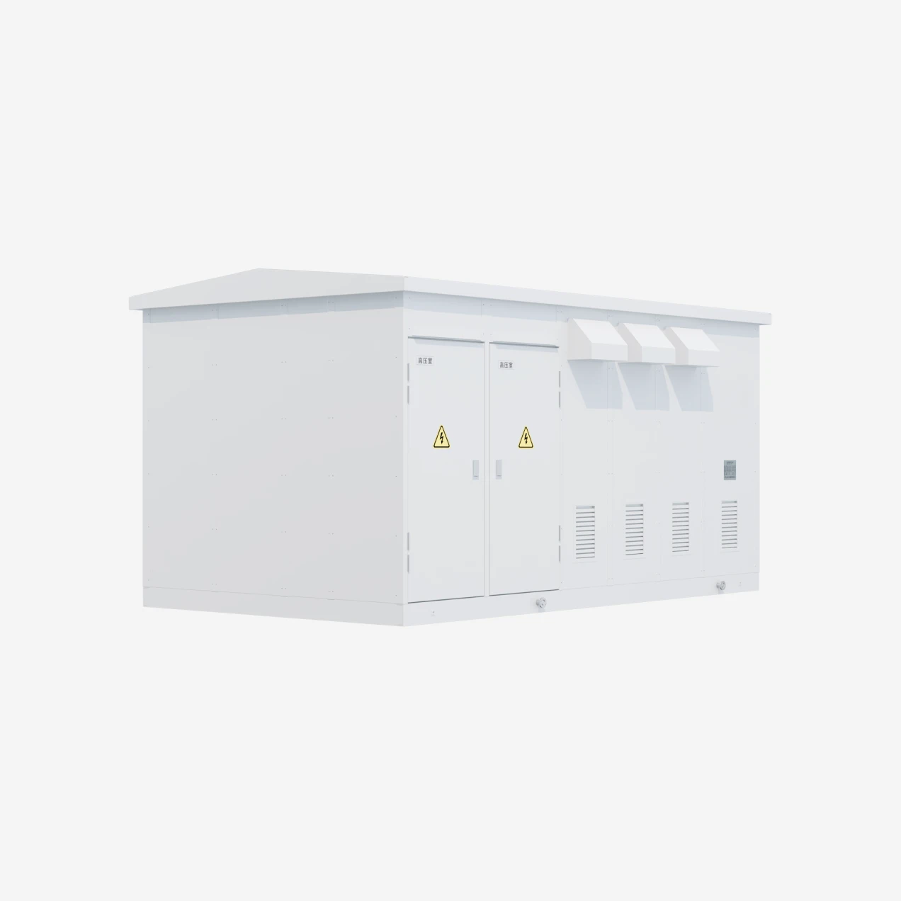
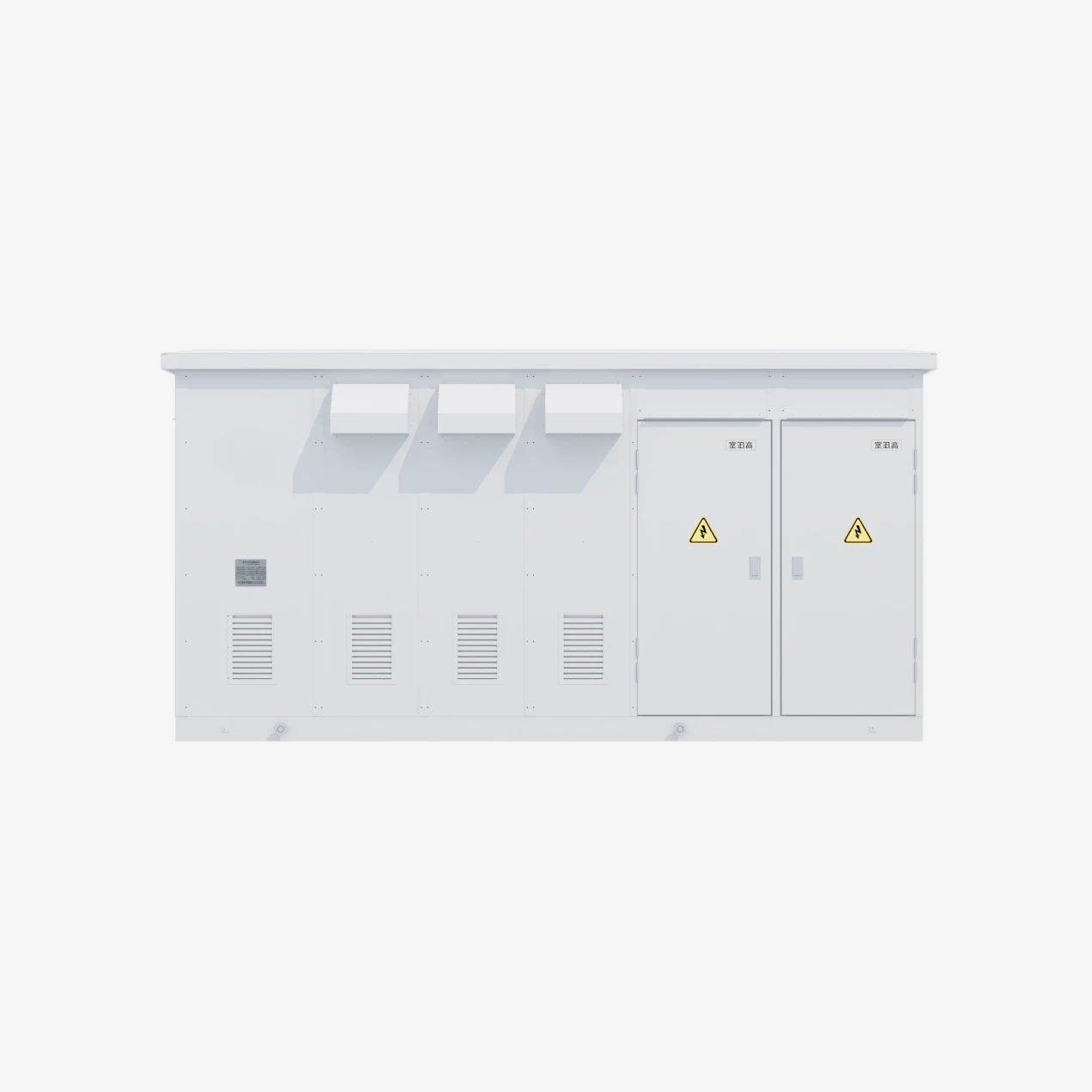
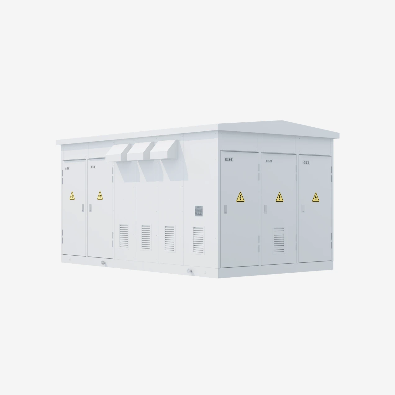
Three-Compartment Isolation Architecture
The defining structural feature of the European-style compact substation is the physical separation of HV, transformer, and LV compartments within a single enclosure. Each compartment has its own access door, ventilation system, and internal lighting. HV and LV cable entry points are located in dedicated trenches or gland plates to prevent cross-contamination of wiring. The transformer compartment is sized for either oil-immersed or dry-type units, with oil containment channels and drain points provided when oil-filled transformers are specified. Fire-resistant barriers between compartments prevent thermal propagation in the event of an internal fault, and pressure relief vents on the transformer compartment roof protect the enclosure structure from overpressure events.
This layout contrasts with American-style pad-mounted substations, which typically integrate HV fuses and switches within the transformer tank itself. The European approach provides independent access to each voltage level, simplifies fault isolation, and supports a wider range of HV protection schemes including RMU ring networks, dual-source transfer, and relay-protected breaker feeders.
HV Compartment Configurations
The high-voltage compartment is designed around a 650mm or 800mm wide switchgear bay. Standard configurations include SF₆-insulated ring main units (RMU) for looped network applications, vacuum load break switches with fuse protection for radial transformer feeders, and vacuum circuit breakers with protection relays for critical or high-fault-level installations. All HV switchgear is factory-installed, wired, and functionally tested before shipment. Cable terminations support both XLPE incoming feeders and overhead line connections through roof bushings. Earthing switches and voltage indicators are interlocked with compartment doors to prevent access under energized conditions.
Transformer Compartment Design
The transformer compartment accommodates distribution transformers rated from 30kVA to 1600kVA with either oil-immersed or dry-type insulation. Oil-immersed units are installed on a raised steel grid floor with an integrated containment bund sized to 100% of transformer oil volume plus rainfall allowance. The bund drains to a sealed sump with oil-water separation capability. Dry-type transformers are mounted on insulated supports with forced-air ventilation when specified for high-capacity or high-temperature installations. Both configurations include temperature monitoring, pressure relief (oil type), and lifting points for future replacement without removing the enclosure roof.
Sound attenuation is addressed through composite wall panels with acoustic insulation, reducing transformer noise propagation to surrounding areas. This is particularly important for urban residential installations where noise limits may apply.
LV Distribution and Metering
The low-voltage compartment houses the distribution panel with incoming circuit breakers, busbar systems rated up to 4000A, and outgoing feeder breakers sized to the load schedule. Standard panels include MCCB outgoing feeders; ACB incomers are available for larger capacities. Metering compartments with CTs, PTs, and multifunction power meters can be fitted for utility billing or internal energy management. Optional capacitor banks for reactive power compensation and harmonic filters for non-linear loads are factory-integrated and wired to the LV busbar.
Cable outgoing is managed through bottom-entry trenches or rear-mounted gland plates. The compartment layout maintains adequate working clearances for breaker withdrawal and busbar inspection, complying with IEC 62271-202 access requirements.
Enclosure and Environmental Protection
The substation enclosure is constructed from folded galvanized steel sheet with polyester powder coating, aluminum alloy extrusions, or stainless steel for corrosive environments. Wall and roof panels are insulated with rock wool or polyurethane foam to limit internal temperature rise and reduce noise. The IP55 protection rating is verified through factory testing: dust ingress protection against harmful deposits and water jet resistance from any direction. For coastal or heavily polluted environments, enhanced corrosion protection and filtered ventilation systems are available.
The enclosure base frame is designed for forklift handling and crane lifting, allowing transport as a single unit. Foundation requirements are limited to a level concrete plinth with embedded anchor bolts; no building structure, cable trenches, or fencing are required beyond local regulations.
Standards and Factory Testing
Design and manufacturing comply with IEC 62271-202 (high-voltage/low-voltage prefabricated substations), GB/T 17467 (box-type substations), and DL/T 537 (ordering technical conditions for 6–35kV substations). Factory acceptance testing includes dielectric withstand on HV and LV circuits, insulation resistance measurement, protective relay functional tests, transformer routine tests, and enclosure IP verification. A complete documentation package including single-line diagrams, general arrangement drawings, test reports, and operation manuals is provided with each unit.