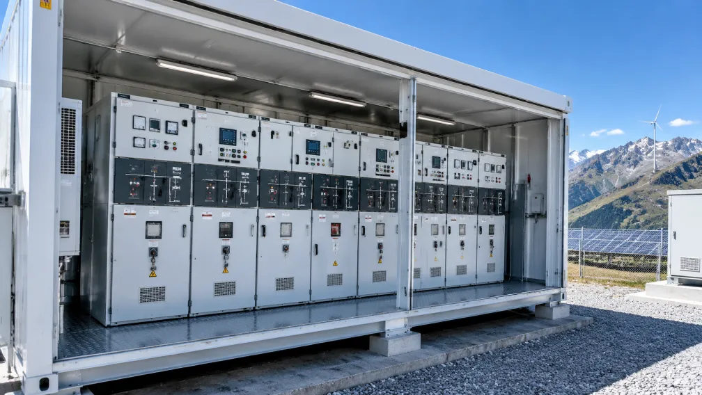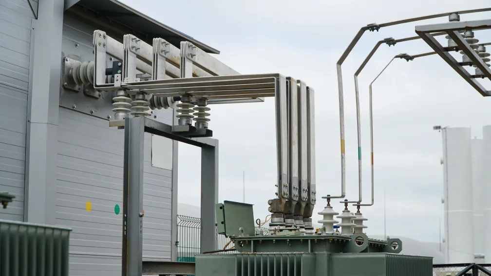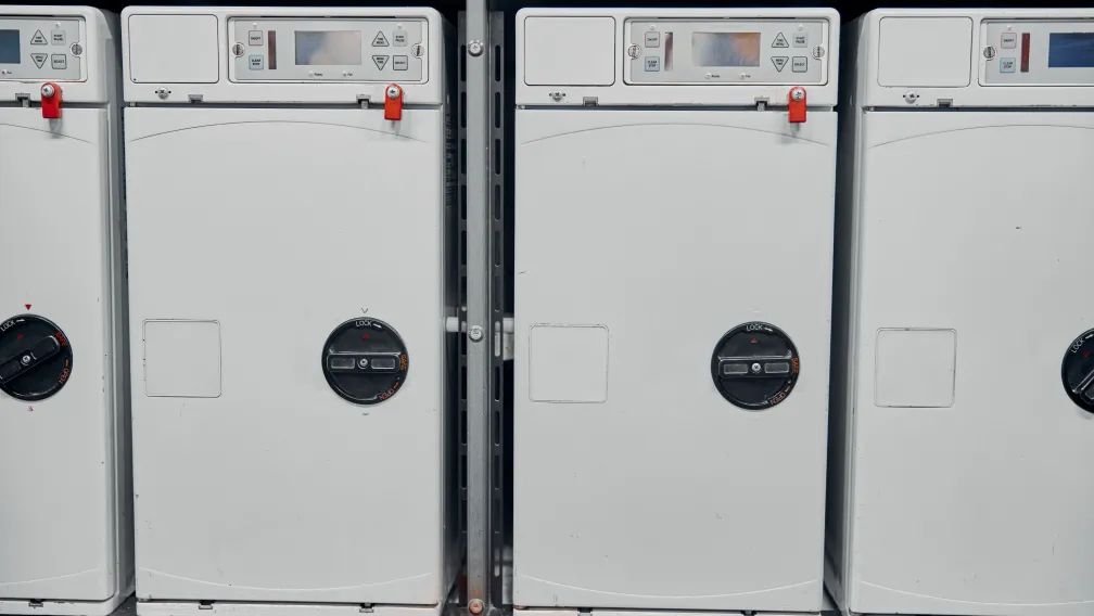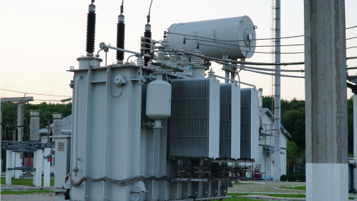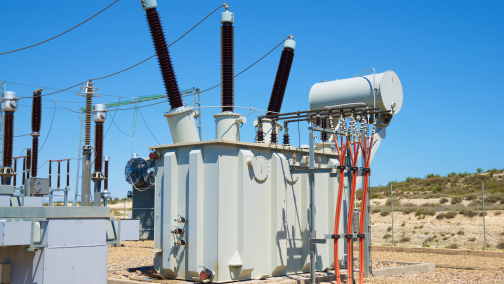


The ring main unit (RMU) is the workhorse of secondary medium voltage distribution. Utilities, industrial parks, commercial developments, and renewable energy plants all depend on RMUs to keep ring networks sectionalized, to protect distribution transformers, and to restore supply quickly after a cable fault. Yet RMU specification is frequently reduced to a voltage and current rating on a single-line diagram, leaving configuration, protection philosophy, and extensibility undefined until the tender stage. This guide sets out the engineering decisions that determine whether an RMU actually fits the network it serves: functional unit selection, transformer protection method, key ratings, insulation medium, and installation format.
The Role of an RMU in Ring Distribution Topology
Secondary distribution networks at 11 kV to 36 kV are commonly built as open rings. Cables run in a loop from a primary substation through a series of load points and back, with one point in the ring deliberately operated open. Each load point is served by a ring main unit carrying at least two ring switches plus a tee-off function feeding the local transformer. When a cable section fails, operators open the ring switches on both sides of the fault, close the normally open point, and restore every healthy load point within minutes. The RMU makes this possible without any breaker at the primary substation needing to see the fault more than once. This topology is why RMU reliability and switching endurance matter more than any single rating: the units switch load current routinely for decades, often in unmanned outdoor locations.
Functional Units and Configuration Codes
RMU configurations are described by letter codes, where each letter is one functional unit inside the assembly. The three building blocks are:
- L (load break switch). A three-position switch (closed, open, earthed) rated typically 630 A that makes and breaks load current and provides visible isolation and earthing for the ring cables. Ring in and ring out functions are almost always L units.
- F (switch-fuse combination). A load break switch combined with high-voltage current-limiting fuses, used to protect the tee-off distribution transformer.
- C (circuit breaker). A vacuum circuit breaker with protection relay, used where the tee-off requires relay-based protection or higher breaking duty than fuses provide.
The most common three-function configuration is CCF or LLF in manufacturer notation: two ring switches plus a fused transformer feeder. A CCV or CFC variant substitutes a vacuum breaker for the fused function. Four- and five-function assemblies add metering modules, busbar sectionalizers, or a second transformer tee-off. The practical rule: define the single-line diagram first, then map each feeder to a letter code, and confirm the manufacturer's designation matches the function rather than assuming the codes are universal.
Transformer Protection: Switch-Fuse Combination or Circuit Breaker
This is the decision that most affects both cost and protection quality. A switch-fuse combination per IEC 62271-105 pairs the load break switch with back-up current-limiting fuses. The fuse clears high-magnitude short circuits in a few milliseconds, limiting let-through energy and protecting the transformer tank from severe fault stress. A striker pin on the blown fuse trips all three poles of the switch simultaneously, preventing single-phasing of the transformer. Because the fuse handles the high fault currents, the switch itself only needs to break load and magnetizing current, which keeps the F function compact and inexpensive.
Fuse selection follows published tables matched to transformer rating and voltage: the fuse must tolerate inrush (typically 10 to 12 times rated current for 0.1 seconds), must not operate on secondary-side faults that downstream protection should clear, and its rated transfer current must remain below the transfer current of the switch. Manufacturers generally rate switch-fuse combinations for distribution transformers up to approximately 1250 to 1600 kVA at 12 kV, with the ceiling falling as voltage rises. Our high-voltage current-limiting fuses for transformer protection and vacuum load break switch-fuse combinations cover this duty range across 12 kV and 24 kV networks.
Above that range, or where the application needs reclosing capability, transformer differential or restricted earth fault protection, or integration with SCADA-controlled load shedding, the correct choice is a circuit breaker function with a protection relay. The C function costs more and requires auxiliary power for the relay, but it eliminates fuse replacement after faults and gives the operator full trip data.
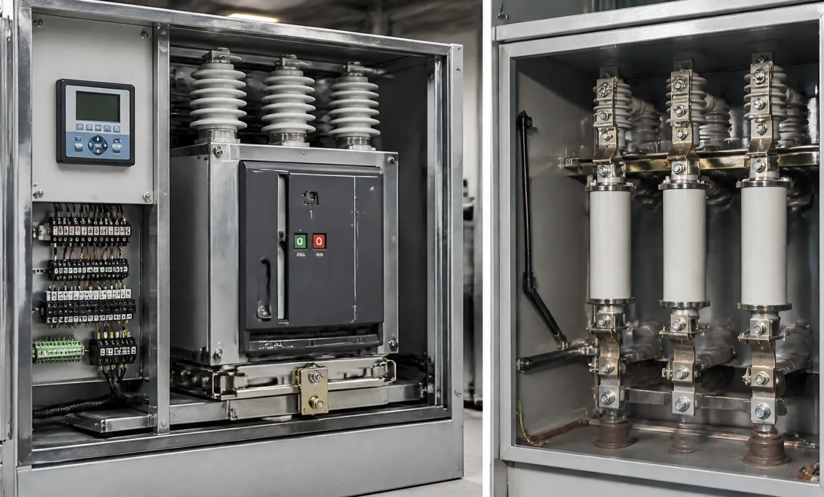
Key Ratings That Belong in Every RMU Specification
| Parameter | Typical specification | Notes |
| Rated voltage | 12 kV / 24 kV / 36 kV | Match the highest system voltage, not nominal |
| Rated current, ring switches | 630 A | Ring feeders; 1250 A for busbar coupling variants |
| Rated short-time withstand | 20 kA / 3 s or 25 kA / 1 s | Verify against the network fault level study |
| Rated lightning impulse withstand | 95 kV (12 kV class), 125 kV (24 kV class) | Per IEC 62271-1 insulation levels |
| Internal arc classification | IAC AFLR, 20 kA / 1 s | Per IEC 62271-200; define arc duration and venting path |
| IP rating | IP4X enclosure / IP67 gas tank; IP54 outdoor housing | Outdoor units need verified condensation control |
Two of these rows deserve emphasis. Short-time withstand must come from the project fault study, not from habit: urban rings fed from large primary substations increasingly exceed 20 kA. Internal arc classification defines what happens to an operator standing at the front, sides, or rear of the unit if an internal fault occurs; AFLR classification with a defined venting direction is the correct minimum for publicly accessible installations.
Extensible Versus Non-Extensible Design
A non-extensible RMU houses all functions in a single sealed tank, typically up to five functions. It is the most compact and economical format and suits defined networks with no planned growth. An extensible RMU provides screened bushings on one or both sides, allowing additional panels to be coupled on site without gas handling or floor modification. Specifying extensibility costs little at tender stage and protects the network against an expensive retrofit when a new customer or feeder joins the ring later. For industrial estates and phased developments, extensible designs should be the default.
Insulation Medium in New Procurement
Traditional RMUs use SF6 gas as the insulating medium inside a sealed stainless steel tank. With Regulation (EU) 2024/573 now prohibiting SF6 in new medium voltage switchgear up to 24 kV from January 2026, buyers supplying European projects must specify SF6-free designs: vacuum interruption combined with dry air insulation, or fully solid-insulated switchgear construction with epoxy-encapsulated switching elements. Outside the EU, SF6-insulated gas-insulated RMU designs remain available and compliant, but project owners increasingly specify SF6-free equipment to remove future regulatory and end-of-life obligations from the asset.
Installation Environment and Enclosure Selection
Indoor RMUs installed in dedicated switchrooms normally operate in IP41 or IP42 housings, since the building provides weather protection. Outdoor units require IP54 enclosures with verified anti-condensation measures: space heaters, controlled ventilation, and sealed cable trenches. Coastal and industrial atmospheres justify stainless steel or heavily coated enclosures, and sites above 1,000 meters need altitude correction for any air-insulated compartments. Sealed-tank designs are unaffected by altitude and pollution because the live parts never see ambient air, which is one reason gas-insulated and solid-insulated RMUs dominate outdoor ring applications. Where floor space or civils budgets are constrained, integrating the RMU into a prefabricated compact substation removes the need for a dedicated switchroom entirely.
Selection Checklist for Tender Documents
A complete RMU enquiry should state: single-line diagram with letter-coded functions; system voltage, fault level, and duration; transformer ratings and preferred protection method with fuse tables; internal arc classification and venting arrangement; indoor or outdoor installation with IP requirement; extensibility requirement; motorization, RTU, and SCADA interface provisions; cable type, size, and termination standard; and the applicable IEC 62271 series type test reports. For most secondary distribution rings feeding transformers up to roughly 1250 kVA, the standard answer is a three-function extensible RMU with 630 A load break ring switches, a switch-fuse tee-off, 20 kA short-time rating, IAC AFLR classification, and sealed-for-life construction. Deviations from this baseline should each trace back to a documented network requirement.
Conclusion
Correct RMU selection comes down to four decisions: the function codes that implement your single-line diagram, fuse versus breaker protection for the transformer tee-off, verified ratings from the fault study rather than catalog defaults, and an insulation medium aligned with the regulations of the destination market. Getting these right at specification stage costs nothing; getting them wrong surfaces as protection miscoordination, failed type test documentation, or equipment that cannot be extended when the network grows.
Elecstellar manufactures ring main units and medium voltage switchgear across 12 kV to 40.5 kV, including SF6, SF6-free, and solid-insulated configurations, with type test reports to IEC 62271-200 available for tender submission. Our RMUs are also integrated into factory-assembled compact substations for fast-deployment projects. To review configurations against your single-line diagram, contact our engineering team.
-

STELLAR
Switchgear & Power Transformer ManufacturerSTELLAR designs and manufactures switchgear, transformers, and complete power distribution equipment from our China facility, serving utilities, contractors, and distributors in 50+ countries. Every technical article on this site is reviewed by our in-house engineers to ensure accuracy against IEC standards and real project practice.